
Installation
What are the steps for installation?
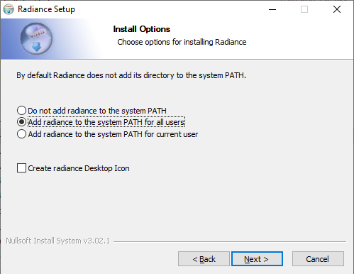
- Right-Click the MBSDaylightForAutocadSetup.exe file and Select Run as administrator. This ensures future software updates can be obtained without admin privileges.
- It installs .Net framework and Radiance dependencies along with the MBS Daylight for Autocad DLL and settings files.
- Remember to Select Add radiance to the system PATH for all users.
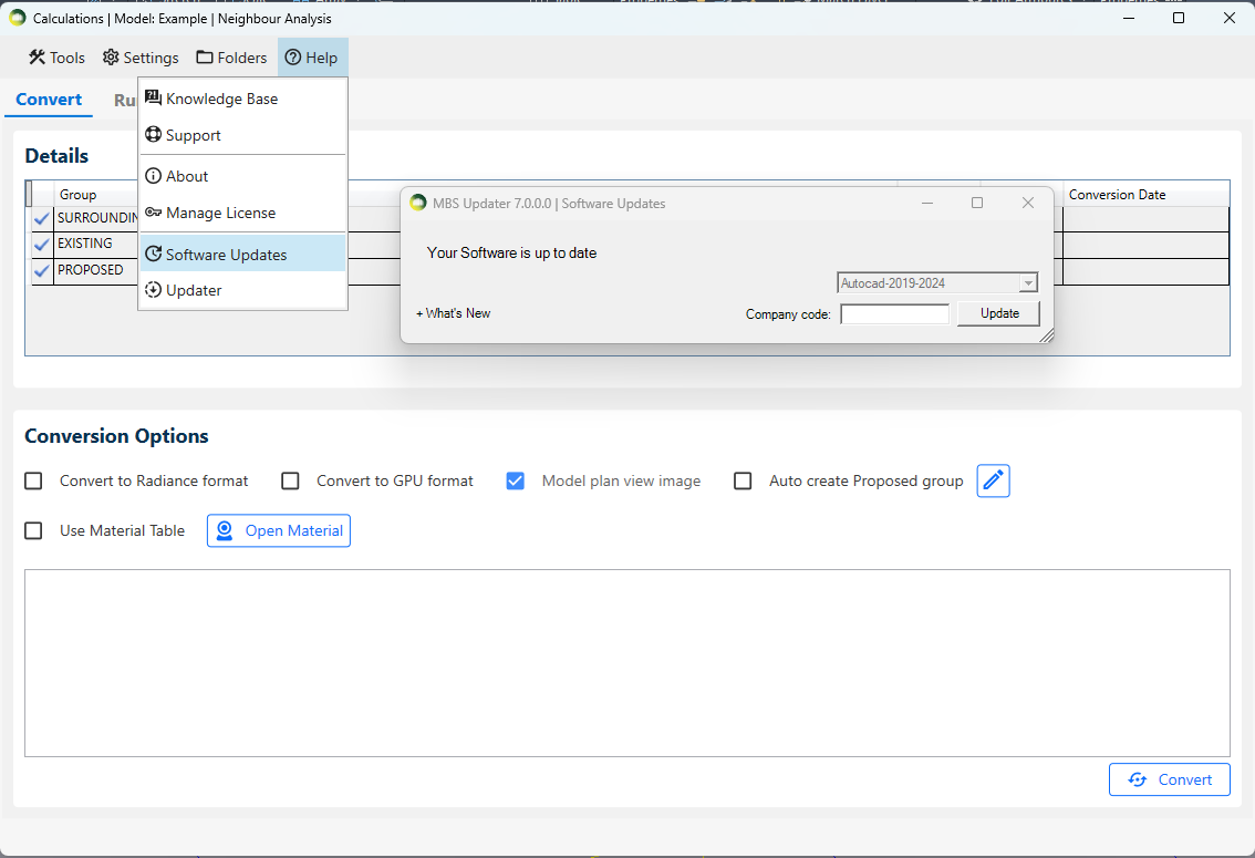
What are the steps for updating the software?
- Software Update dialog will automatically open on the first run after the installation.
- For future updates, follow the below steps
- Open the MBSCalculation dialog > Help > Software Updates > Update
- Autocad and any MBS Calculation service consoles must be restarted after the update.
- What’s New expander can be clicked to check the list of the latest changes.
Why does the MBS toolbar not appear after installation?
- In some cases, it may remain hidden after installation.
- Go to Autocad Menu bar > Tools > Toolbars > MBS Daylight For Autocad
- Then Tick Both MBS Daylight For Autocad and MBS Daylight For Autocad Layers to enable it.
Licensing
How to activate the Trial License?
The Trial license is automatically activated when any of the MBS dialog is open for the first time.
- The license will be valid for 7 days from the time of activation and gives access to Full features of the Plugin.
To Check the status of the Trial License
- Click on the License menu on the MBS toolbar.
- It can also be opened from MBS Calculation Dialog > Help Menu > Manage License
- Press Check
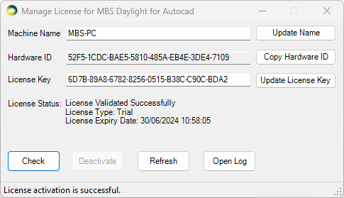
How to upgrade to the Subscription License?
- Once you purchase a Subscription license from MBS, We will provide you with a License key.
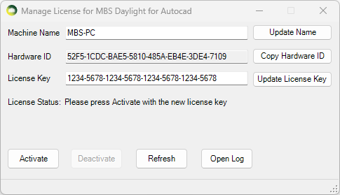
- Open the Manage License dialog
- Paste the key onto the License Key textbox and Press Update License Key.
- Press Activate. (Internet connection is required).
- The software validates the license regularly with our license server to allow the license to be used on multiple computers.
- Sometimes the firewall or anti-virus restrictions can block the license activation and validation. Contact us for details about the license server address which the IT team might need in order to allow the activation and validation.
* The plugin can be installed and used on multiple computers. There is a 30 min cooling off period once the plugin is used on one computer before it can be used on another computer.
How to transfer the Subscription License to another computer?
- The plugin can be installed and used on multiple computers.
- There is a 30 min cooling off period once the plugin is used on one computer before it can be used on another computer.
- If the plugin needs to be used before the cooling off period, the license needs to be de-activated from the computer where it was last used.
- Open the Manage License dialog.
- Press Deactivate
- Once it is de-activated, it can be activated immediately on another computer.
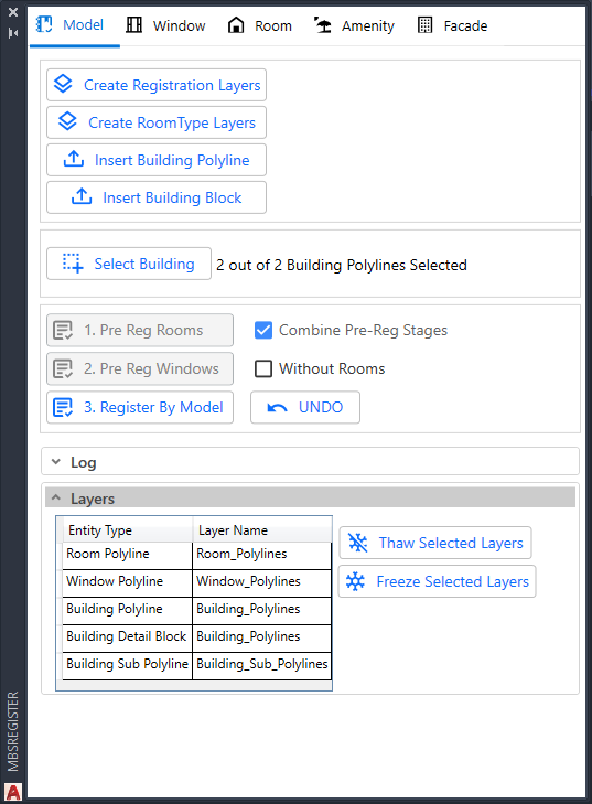
Register By Model
List Of Layer Names
- Room: Room_Polylines (Can also use Room_Polylines_Bedroom or Room_Polylines_Living Room to specify room type during registration)
- Window: Window_Polylines
- Building Outline: Building_Polylines
- Building Detail Block: Building_Polylines
- Extra Building Outline: Building_Sub_Polylines
Building Detail Block
- Click on Insert Building Block button on the Register Model section on the Register Dialog.
- Select the building polyline to insert the building detail block.
- Type the name of the building on the Building name text box.
- Then Select the start floor in the building from the combo box.
If the floor name needed is not present on the list, Edit the Floor Names list to add the name and repeat this process. - It will be added to the Building_Polylines Layer.
Registration By Model Steps
- Combine Pre-Reg stage check box
This disables the buttons for pre reg Step 1 and Step 2. The register by model will be performed in one go with Step 3 directly. The pre reg rooms and windows step are done in background and can be enabled by unticking the Combine Pre-Reg stage option if necessary for debugging. This option will also work when Without Rooms option is checked. - Step 1: Pre-Reg Rooms
- Updates building names from blocks with building name and starting floor names.
- Determines Building and Floor for Rooms based on Building_Polylines and Z of room.
- If current Room is higher than 0.5m(this value can be changed if rooms in same floor are in various height) than the previous Room then it is put on a new floor.
- Step 2: Pre-Reg Windows
- Determines Building and Floor for Windows based on Building_Polylines and average height of Pre-Registered Room_Polylines in a floor.
- If the centre of a window is higher than or equal to the average height of rooms in the current floor and smaller than the floor above then it is put on current floor.
- All windows whose centre is higher than or equal to average height of the rooms in the last floor they are put that last floor.
- If Without Rooms is ticked, the window floors are determined using a fixed height of 2.5m. If current window’s centre is higher than 2.5m of previous window’s centre, current window will be put on new floor.
- Step 3: Registration
- Registers windows and rooms to the floors and building determined during pre-reg steps
- Attaches windows which are within the search tolerance (default: 1m) range of rooms to them.
- Rooflight windows will be attached to rooms if they are within the room even if they are further away than the search tolerance.
- If any window is not correctly attached to room, it can be manually attached from Register dialog /Update Mode /Room. Update.
- Summary will show count of room/window polyline which are not registered windows which are facing inside room windows, which are not attached to rooms and windows which are slightly inclined.
- Windows in Odd Shaped Walls
The building polyline can be drawn in much simpler way.
Building polyline doesn’t have to follow the window polyline too closely as long as it is closest to the window centre in any directions.
- Notes
- The building polyline determines start and order of window and room names.
- Floor name combo box must have enough entries for all floors to be registered and must be on correct order
- Room and window names will be automatically added using the current naming convention if the list does not have enough entries.
- There is no need to add building names by Editing the Building Names combo box list as the names from the building detail blocks are automatically added after registration.
- Each step can be undone using single Undo as a new Undo group is created for every step
Register FAQs
Register by Model FAQs
What layer names are used by Register by model to detect the polylines?
The Register Model section – Layers tab shows list of all the layer names. Create Registration Layers button creates all the required layers in one go.
Can only windows be registered on their own?
Yes. Without Rooms option should be ticked.
Can Rooms be registered on their own?
Yes. If windows are already registered with same building and floor address.
Perform 1. Pre-Reg Room then 3. Register by model. Windows will be linked to the rooms
No. If windows are not registered with same building and floor address.
How can window/room address be updated if they are added/removed after the initial registration?
In Modify Dialog (MBSMODIFY command), Re-Number button allows to renumber windows and rooms. Building polyline and building name block are required. Re-Numbering can be done for partial floor, single floor or entire building.
Can window/room name be started from a different location in the building?
The first window and the order is determined by the starting point and order of building polyline vertices. Redraw the polyline to match the requirement and perform renumbering.
Why could not the building name and/or starting floor be determined from the building detail block?
- The block must be on Building_Polylines layer.
- The block’s base point must be within the outlining building polyline
- The starting floor name must already exist on the floor name combobox(loaded from FloorList.txt)
What are the steps to specify Room Type via Room polyline layers for Registration?
- Create layers for room type in the strict format of Room_Polylines_Roomtype e.g. Room_Polylines_Bedroom
- In Register dialog (MBSRegister Command), the Model tab has Create RoomType Layers button which can create the layers from the list of room types.
- It is also possible to set layer colors for room type layers.
- The room type name must be present on the RoomType.txt file. The list can be viewed on Register or Modify dialog > Room tab > Room type combobox.
- Room type will be set based on the layer name of the room polyline during registration.
- It is supported by both individual room registration and register by model
Avoid these characters (‘<‘, ‘>’, ‘^’, ‘”‘, ‘:’, ‘?’, ‘*’, ‘|’, ‘;’, ‘=’, ‘,’, ‘@’) in the room type name as it is not supported by Autocad on layer names
What are the steps to modify shape of registered Room polylines?
- Change the shape of the Room polyline
- Query the Room by address or Select polyline for the concerned Room(s) on Room tab of Modify dialog.
- If the room was already listed when the changes were made, Re-Query the room
- Modify dialog > Room Tab. Update
- DRAWROOMGRIDPOINTS command can be used to confirm shape change has been updated correctly.
How to specify the values for the Maintenance Factor (dirt factor)?
It is based on the BS 8206-2:2008 guideline (Lighting for buildings. Code of practice for daylighting).
Maintenance factor = 100% – (loss% x exposure multiplier x special exposure multiplier) e.g. 100% – 8%x1x1 = 92% (0.92)
- The default value used are loss of daylight = 8 (Urban, Residential), exposure = 1(Normal exposure, Vertical), special exposure = 1(not used).
- The exposure multiplier depends on the exposure type and the window inclination.
| Exposure | Exposure multiplier | ||
| Vertical glazing | Inclined glazing | Horizontal glazing | |
| Normal exposure | x1 | x2 | x3 |
| Exposed to heavy Rain | x0.5 | x1.5 | x3 |
| Exposed to snow | x1 | x3 | x4 |
- For example, Glazing transmittance of BRE recommended clean, clear double glazing with a low emissivity window is 0.68.
- In the old version of software, this value used to be modified to include the maintenance factor and value of 0.63(0.68 x 0.92) would be used as glazing transmittance.
- In the new version of software, full glazing transmittance of 0.68 should be used instead of 0.63 to avoid maintenance factor to be applied twice.
Note: - Would the result change if model registered with old version is used on new version of software?
No. The maintenance factor will be assumed to be 1 for old version windows to keep the results same. However, it is important to modify the glazing transmittance if any maintenance factor is included with it when the windows are updated on the new version of software. - Is it possible to not use the maintenance factor completely to avoid any mix up?
Yes. If the loss of daylight is set to 0. The maintenance factor will remain 1 which will work like the old version of the software
How to specify offset values for VSC, APSH, SE and ADF?
- Offset value should be positive to go towards the room and negative to go away from the room
- For example, Assuming VSC and APSH calculation point is on the outside of a 0.3 meter wall, ADF calculation point is on the mid-point of the wall, the offset can be set as below
| Window Location / Calculation | VSC & APSH Offset | ADF Offset | SE Offset |
| Window on Outside Wall | 0 | 0.15 | 0.3 |
| Window on Centre of Wall | -0.15 | 0 | 0.15 |
| Window on the Inside Wall | -0.30 | -0.15 | 0 |
What are the steps to restore Room-Window link after copying rooms and windows?
- Copy the required Rooms and windows
- Paste the copied rooms and windows
- Modify dialog (MBSMODIFY command) > Room >
 > Copy Room-Window Link (Select the original rooms)
 - Modify dialog (MBSMODIFY command) > Room > > Paste Room-Window Link (Select the copied rooms and windows)
- Modify dialog (MBSMODIFY command) > Room to update the room grid points.
- DrawRoomGridPoints command should be used to confirm the room has been updated correctly.
What are the steps to copy amenity to another model?
- Copy the required Amenities and Paste to a new model
- Do not copy the label and result contours
- Modify dialog (MBSMODIFY command) > Amenity. Update the Amenity
- Use DrawAmenityGridPoints command to confirm the copy is done correctly
Room polyline
- Must be
 2D Lightweight polyline
- Horizontal
- Coplanar
- Must not be
- 3D polyline
- With a Curve
- Sloped
- Non-Coplanar
Window polyline
- Must be
- 2D Lightweight polyline
- Horizontal Or Vertical Or Sloped
- With a curve
- Coplanar
- Must not be
- 3D polyline
- Non-Coplanar
Amenity polyline
- Must be
- 2D Lightweight polyline
- Horizontal Or Sloped
- Coplanar
- Must not be
- 3D polyline
- With a Curve
- Non-Coplanar
Why is Amenity registration taking a very long time?
- The default grid spacing of 0.3 means there could be thousands of calculation points within the area which causes the registration time to increase. Grid spacing can be increased slightly to improve the registration time.
Can room/window groups be automatically created?
- RG_ALL, WG_ALL and AG_ALL are created automatically once you close the register dialog after registering the relevent entities i.e. room, window and amentity.
- It is not necessary to add room, window or amentity manually each time you register. These groups are updated on fly with all entities (room, window or amentity) when running calculation.
- Similarly, there are options to create or clear the groups for each entity type in modify dialog. For this follow the following steps:
- Open modfiy dialog from the menu or run MBSModify command.
- Click on relevent tab i.e. Window / Room / Amentity / Facade
- Then click on
 icon.
icon.
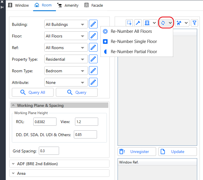
Renumbering Windows/Rooms
Renumbering can be useful if windows and rooms are added or removed from the model after the initial registration. It can also be useful if the numbering of the windows needs to start from a different position. Renumbering can be done for All Floors, Single Floor or Partial Floor in a building. Single and All Floor renumbering options need the building polyline and building name block (Both of them must be on the building_polylines layer).
Renumber Options are in the Modify Dialog Room tab.
All Floors
Once Re-Number All floors option is selected, a prompt is given to select the building polyline. Then the rooms and windows in all floors above the starting floor (as specified in building detail block) will be renumbered based on the selected building polyline. This doesn’t alter the floor references of rooms and windows.
Please note that if there are any window/room within the building polyline but have a different building address to the one in building detail block, they will not be included in the renumbering process.
Single Floor
Once Re-Number Single floor option is selected, a prompt is given to select the building polyline. Then, another prompt is given to Select one registered window in the floor where the renumber is to be done. Then the rooms and windows in the floor of the selected window will be renumbered based on the selected building polyline. This process considers windows/rooms which are already registered in the floor and building address only.
Please note that if there are windows within the building polyline and in the same height as other windows in the selected floor but are registered with different floor or building name, then they will not be part of the renumbering process.
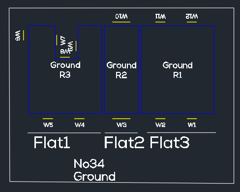
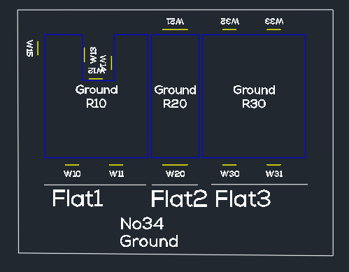
Partial Floor
Once Re-Number Partial floor option is selected, a prompt is given to select a reference polyline (this can be an open polyline different from the building polyline). Then, another prompt is given to Select the windows to be renumbered. Then, Starting window number can be entered without the prefix e.g. 10 for W10. Once window renumbering is complete, prompt is given to confirm if the rooms should be renumbered too and starting room number can be entered if affirmed.
This option is useful if the windows need to be renumbered in noncontinuous manner for flats within the same building as shown in image.
Please note that the partial renumbering cannot automatically handle duplicates if existing window which is not being renumbered uses the same number. In order to avoid duplicate issue, partial renumbering should be done for higher window numbers. For example, Let’s say Flat 1 window need to start from 10, Flat 2 windows from 20 and Flat 3 windows from 30. If Flat 1 is to be renumbered first and window numbers will conflict with W10 on Flat 2 and W11,W12 on flat 3. However, if Flat 3 is renumbered first, followed by Flat 2 and then Flat 1 the conflict can be completely avoided as shown on the image below.
Cutback
- Open cutback dialog by entering MBSCutback command or By pressing the Cutback icon on the mbs tool bar.
- Select group
- Select Sky type. For ROL cutback Sky should be set to Uniform.
- Orientation is the surface orientation where the calculation point lies on.
Set the Orientation to Vertical for Windows, and Horizontal for ROL
Although ROL calculation is for a point on a horizontal surface(working plane), the rendered image for points deep in the room might come in low resolution.
You may pick Vertical orientation in this case for ROL to get a higher resolution Waldram image. - Select Room or Window from the box and press Select.
If Room option is selected, a point within the room needs to be selected too. - Press “Create Diagram” to render Waldram image.
To start drawing shape press button. There are three tools available to draw shape:
- Horizontal mode: draws droop line on the diagram. The result is straight horizontal line in 3d.
- Vertical mode: draws vertical line.
- Freehand mode: draws polyline on the diagram with any number of segments.
To close the shape at specified high, press and pick a point on the image. The shape will be closed by adding three perpendicular segments as in the image below.
You may press “Cut diagram” button to cut the drawn shape on the image and update Sky Component value. This does not create/cut the 3d model. Instead it can be used to check whether the resulting Sky Component is close to the desired value.
To draw new shape it is suffice to press Erase button. - Pressing “Create 3D Object” will create the 3d object(s) in the model from the shapes on the diagram (The user can later subtract the created object from proposed objects). Tick “Subtract from Proposed” to automatically subtract the shape on the diagram from the 3d proposed objects. The subtracted object is put into “CutbackInterference” layer in red colour.
Tick “Re-Create diagram” to automaticaly reconvert and create the new diagram. In case of room new contours are calculated.
Material Settings
About Material Dialogue
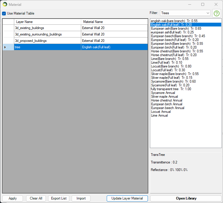
Material Dialogue can be opened by clicking on the material dialog icon on the tool bar or by clicking the Tools Menu then Materials. Using of the Material Table requires enabling the option by ticking the Use Material Table box on the Materials Dialogue.
– Using Material Table Mode
The material table is empty for a new project. The list is populated with the materials based on the layer colour RGB value when the model is converted for the first time. It an then be modified WITHOUT a need to re-convert the model. Therefore this gives more flexibility on experimenting different materials and parameters for an analysis.
Default diffuse material with reflectance read from layer colour (r = 51, g = 51, b = 51 translates to 0.279, 0.279, 0.279) is used for objects on that layer. RGB gamma correction is applied in order to make the rendered image look similar to when viewed in a Monitor.
Clearing the material list and Importing the material list from another project requires model reconversion. This is also the case on making any change to the model, like adding deleting objects or changes to the object layer.
– Not Using Material Table Mode
Default diffuse material with reflectance read from layer colour (r = 51, g = 51, b = 51 translates to 0.279, 0.279, 0.279) is used for objects on that layer.
How to prepare a model for Assigning the Materials?
Put objects in the model to their corresponding layers. Normally for indoor calculations like Climate or Daylight Factor the scene is divided into two groups of objects, external obstructions and room internal surfaces.
and What happens to registered Windows Glazing Transmittance?
In AutoCAD, separating floors, walls and ceilings objects and put them in their layers (e.g. all walls objects to “wall” layer) can be a challenge.
Any solid object has to be exploded first to access the individual surfaces. Care must be taken to put back the exploded objects back into their original ClassicGroup.
The ExtractRoomSurfaces command is a utility command in AutoCAD that automatically extracts floors, walls and ceilings and put them in corresponding layers.
Updating Material for Layer
Updating the Material for Layer(s)
- Select one or more rows from the layer – material list on the left hand side for which you want to update the material.
- Select the desired material from the Material list on the right hand side and press Edit Material for Selected items.
- Press Update Layer Material.
- Repeat steps 1 – 3 as necessary for the layers.
- Press Apply and Close the dialog.
- Updating the materials this way doesn’t require model reconversion
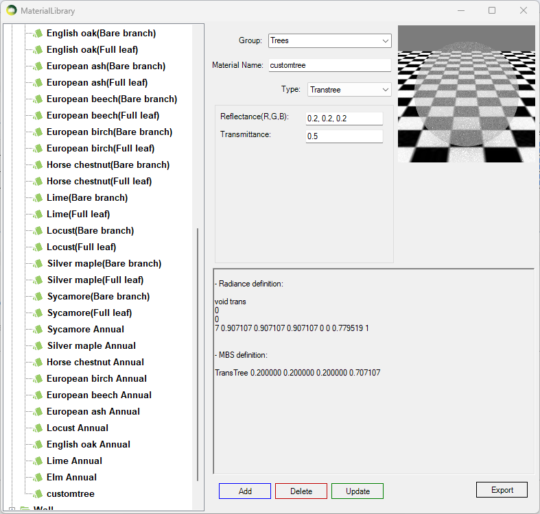
Adding New Material
Adding New Material to the library
- Click on the Open Library button
- Select a existing Group or Type a new group name for the material on the Group combo box.
- Type a unique name on the material name text box.
- Select a Material Type from the Type combo box. See below for detail on types.
- Assign material properties on the relevant text boxes.
- Press Add and Close this dialogue.
- Remember to Press Apply on the Material dialogue.
- Diffuse surface reflects light uniformly over the entire reflecting hemisphere. A Lambertian (or diffuse) surface appears equally bright from all viewing directions.
The reflectance parameter represents the fraction of the incident energy that is reflected at a surface. The parameter has three components which range from 0 to 1. - Mirror (specular reflection) surface only reflects light in one specific direction.
- ThinGlass is a special case of dielectric, infinitely thin and therefore does not change the transmitted ray direction. It is modelled as a single surface. The default refractive index is 1.52.
Transmittance is the ratio of the total transmitted light to the incident light which includes multiple inter-reflections in a layer of glass.
The parameter is a single value from 0 to 1 – Reflectance field is disabled as it is a function of angle, refractive index of the material and transmissivity.
Transmissivity applies to a single pass of light through a layer of glass and excludes multiple interreflections within the medium.
ThinGlass is translated to Radiance glass material. Transmittance value is converted to transmissivity for the Radiance rad file. - TransTree is a mix of Diffuse Reflection (representing leaves) and Specular Transmission(the gaps). See How to assign the Materials for Trees? for more details.
- Translucent material is a mix of diffuse reflectance/transmittance and perfect/glossy specular reflectance and transmittance. It describes diffuse and glossy specular reflection and transmission through the surface.
Translucent parameters are well described in this link: http://www.schorsch.com/en/software/rayfront/manual/transdef.html - BSDFRadiance material, only valid on Radiance method, is to define material for complex glazing system.
The input is an xml file containing BSDF matrix data. This file can be generated using WINDOW 6.0 BERKELEY LAB application.
Please follow instruction on BSDF Files for Radiance Renderings page.
How to assign the Material for Trees?
Assign Tree Material from pre-defined BRE trees
TransTree is a mix of Diffuse Reflection (representing leaves) and Specular Transmission (the gaps). This material is suitable for simulating trees on BRE (VSC and ADF) or Daylight Factor calculations. The Reflectance value on VSC and ADF calculations only reflects in terms of the colour as no reflected light is accounted for. The Transmittance value is the overall transparency of tree crown as the ray enters and exists the tree volume. Follow the below steps to assign tree material to a layer:
- Put the tree objects with the same transparency to a layer.
- Then Open the Materials dialogue and assign one of the predefined BRE tree materials.
- The trees mentioned BRE Site Layout for Daylight & Sunlight Appendix H Table H1 are included in the material library.
*For Sunlight calculations, they should be run with opaque trees and without trees if necessary
(BRE Site Layout for Daylight & Sunlight Appendix G3)
*For SDA calculations please refer to https://www.mbs-software-uk.com/knowledge/sda-calculation-with-trees/
Creating a custom Tree material
- Open Material dialogue then Press Open Library button
- Create a new TransTree type material
- The reflectance values are used during DF calculation only. It is used for the colour of the tree in case of VSC and ADF calculations.
- The transmittance is converted automatically to consider the overall transparency of the tree crown as the ray enters and exits the tree volume.
- For example 50% overall transparency should be input as 0.5 which will then be converted to 0.707 (√0.5) to adjust for the ray entering and leaving the tree crown. This can also be seen on material preview area.
How to assign the Materials for Balconies?
- Balconies are supported for all calculations including Ray-traced based (Daylight Factor and Climate) and BRE (VSC, APSH and ADF).
- Put the balcony objects with the same transparency to a layer.
- Region or objects with single face should be used.
- Using objects with multiple faces may result in the transparency being applied multiple times.
- If the overall transparency of the balcony modelled as solid is 0.60,
- Then the ThinGlass transparency should be √0.60 i.e. 0.775
- Open Material dialogue then Press Open Library button
- Create a new ThinGlass type material
- The normal transmittance value should be in put as unit value e.g. 0.6 for 60%
- Refractive index of 1.52 is define as default.
- Press Add and Close this dialog.
- Remember to Press Apply on the Material dialogue.
- Then Assign the material to the layer with balcony objects on the Materials tab.
Refer to Updating Material For Layer topic for details.
Legend Settings
Gradient Legend
Gradient legend has five different colour options. All options except MBS and Rainbow allow the users to change the colour. The minimum and maximum values are pre-defined for all the calculation types which support legend creation. The values can be changed by the user if required. Intermediate colours are added to avoid colour contrast between values between two intervals. The breakdown of intermediate colours is as below:
- Two colour: 2 for the given colours and give value from interpolated colours field interpolated colours between them.
- Three colour: 3 for the given colours and give value from interpolated colours field is applied between first and second and second and third colour.
- Custom colour: 11 for the given colours and 10 for the mid colour between them except the last one.
- Rainbow colour: 7 for the given colours and 18 for the intermediate colours between them. (give value from interpolated colours field between each consecutive colour except the last one)
- MBS colour: 11 for the given colours and 10 for the mid colour between them except the last one.
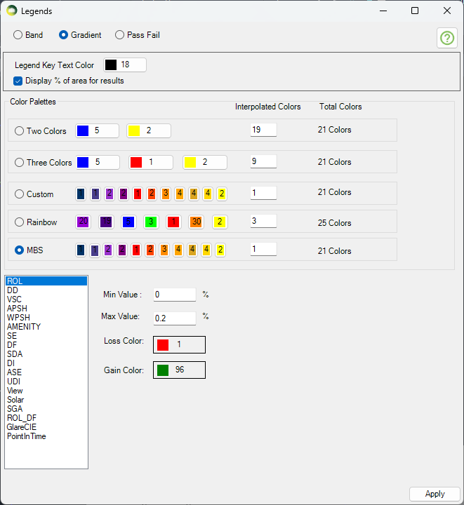
Legend interval
The interval for legend values is created by dividing the min and max values equally to the legend colours. Interval values for legend colours are calculated using the formula (Max value – Min value) / (total colours in legend – 1). The last colour is for all values greater than max therefore (total colours – 1) is used.
For example, The interval of values per MBS legend colour for VSC legend with min of 0 and max of 27 will be calculated as below.
(27-0) / (21-1) = 1.35
Gradient Legend is supported by the following calculations
Facade
- VSC, APSH, SE, Amenity, DF and Solar Radiation
Solids
- VSC, APSH, SE, DF
Result Images
- All room calculation types.
- ROL, DD and Amenity use these colours when Use Image Texture for Room/Amenity Results option in Application Settings is ticked.

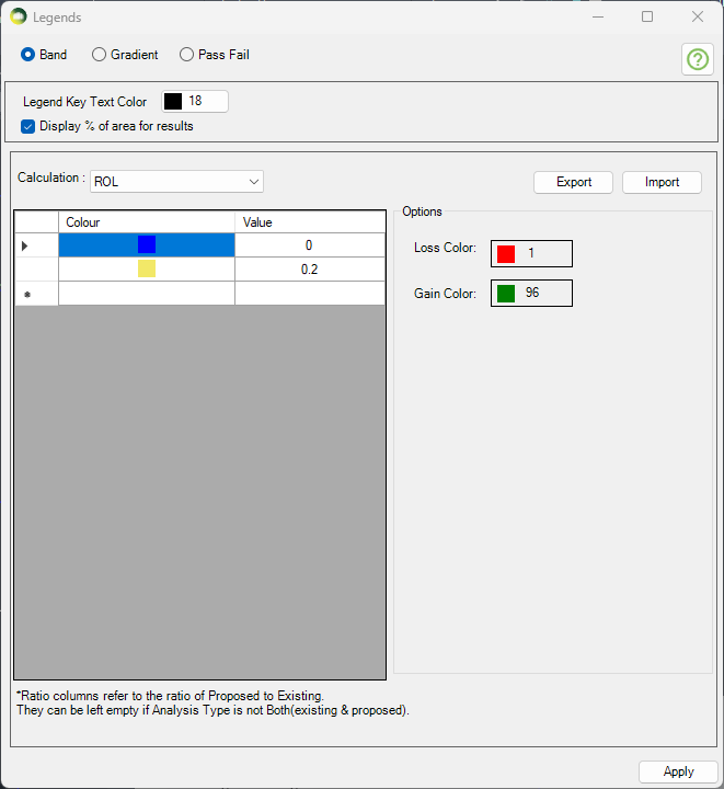
Band Legend (Non-Gradient)
- Select the calculation type on the combo box to define a band legend values.
- Then choose a colour and enter a value. The values must be in ascending order.
- The first value will be the minimum value and last value will be maximum value for any calculation.
Band Legend is supported by the following calculations
Facade
- VSC, APSH, SE, Amenity, DF and Solar Radiation
Solids
- VSC, APSH, SE, DF
- Pass Fail legend will be used for calculation which don’t support band mode.
Result Images
- All room calculation types.
- ROL, DD and Amenity use these colours when Use Image Texture for Room/Amenity Results option in Application Settings is ticked.
Pass Fail Legend
The legend will be created with just three colours for Pass, Nearly Pass and Fail. The colours can be changed by the users. The pass values for VSC and APSH is taken from Project settings Assessment criteria section.
For Example, for VSC calculation
- if the result >= 27 (or) loss < 20 % then it passes
- if the result >= 26 (or) loss < 21 % (Tolerance = 1) the it is Nearly Passed
- otherwise it will fail.
- The legend will show Pass, Nearly Pass and Fail results.
- If the calculation is run for neighbour scheme only one legend is created.
Pass Fail Legend is supported by the following calculations only
Facade
- VSC, APSH, SE and Amenity
- Band legend will be used for DF and Solar Radiation if Pass Fail legend is set
Solids
- ROL, DD, VSC, APSH, Amenity, SE and DF
Result Images
- None
- Band legend will be used if Pass Fail legend is set
Raytracing Settings
Two Monte Carlo backward ray tracer are provided: Path tracing and Radiance software.
- Iterations N: “The error in the Monte Carlo calculation of indirect illuminance will be inversely proportional to the square root of this number:four times more samples are required to decrease the error by half.
- In Radiance option: This value corresponds to ambient divisions “–ad” parameter:
number of rays casted from the surface point to its hemisphere about the normal to estimate the radiance values. Each ray if not absorbed or terminated spawns to N more rays. - In Path tracing: Since no branching happens on each bounce this value determines the total number of indirect paths initiated from the sensor.
- In Radiance option: This value corresponds to ambient divisions “–ad” parameter:
- Indirect Bounces:
- In Radiance: This is the maximum number of diffuse bounces computed by the indirect calculation. A value of zero implies no indirect calculation.
- In path tracing: This is the minimum number of bounces. Russian Roulette probability is applied after reaching this number.
Calculation FAQs
How to name the group?
- Groups must be named precisely. EXISTING, PROPOSED and SURROUNDING
- EXISTING: For buildings/structures which are to be demolished.
- PROPOSED: For buildings/structures which are to be added.
- SURROUNDING: For buildings/structures which stay the same.
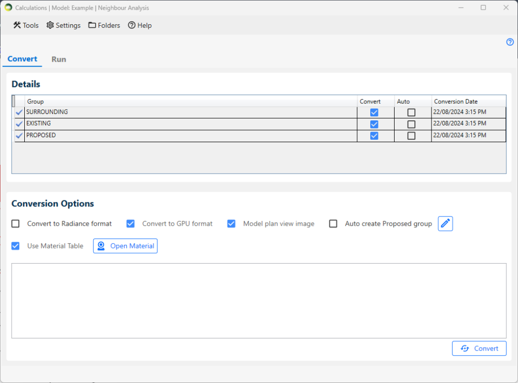
What are the steps to convert the model?
- In the Details section, select the convert checkbox next to the group in which you are interested.
- In the Conversion Options section:
- If you want to run calculations in GPU, tick on the Convert to GPU format option. It requires a compatible graphics card.
- If you want to run DF and Climate calculations in CPU, the Convert to Radiance format option must be ticked. ROL and BRE calculations on the CPU don’t require Radiance conversion.
- Tick the Use Material Table option to use a material table.
- To modify the material table, please click on Open Material button. For more details on the material settings, please refer to Material Knowledge Base.
- Click on the Convert button located at the right-bottom corner of the dialogue.
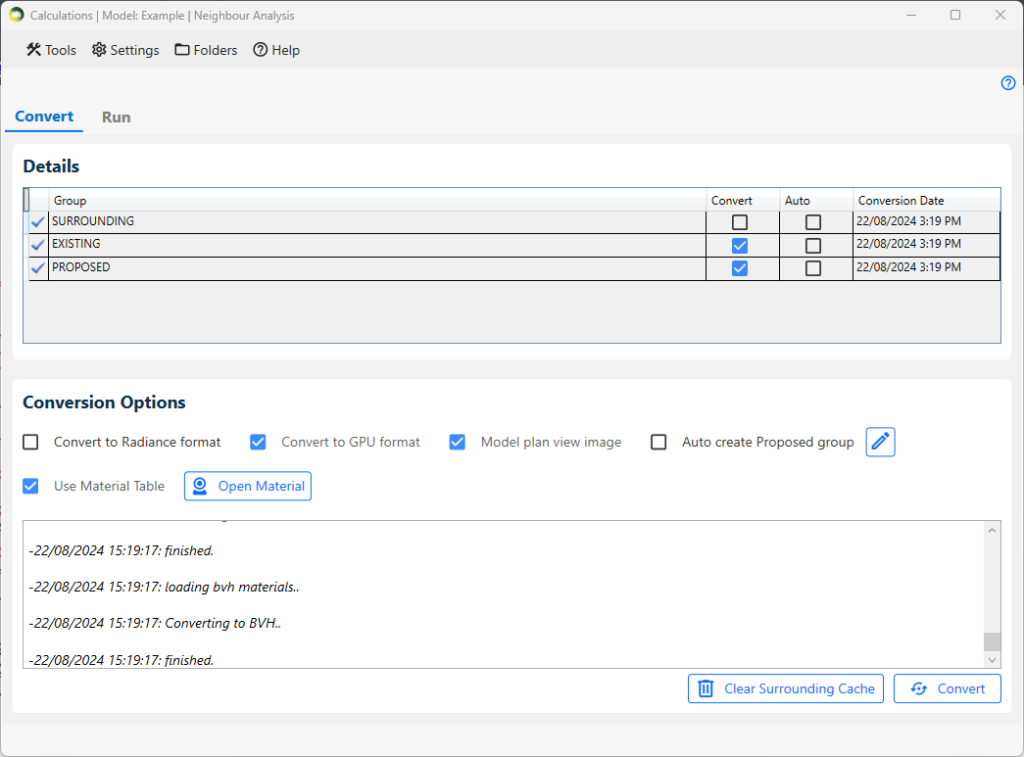
How to avoid re-converting a large surrounding every time?
- The convert option for the Surrounding group must be unticked and the Existing and Proposed group should be ticked before conversion.
- A cache file will be created on the first conversion for surrounding and any subsequent conversion will re-use that.
- If the surrounding group changes, then the cache must be cleared with the Clear Surrounding Cache button and Convert again
Can registered windows be added to any groups?
- Registered windows should be in either the Proposed or Surrounding group based on where they are.
- The same window must not be added to both the Proposed and Surrounding group.
How to recreate proposed group from layers?
- Tick Auto create Proposed group option in Conversion Options section.
- The default layer for proposed group is 3D_PROPOSED_BUILDINGS.
- However, this can be modified and new layers can be added for proposed group. For this follow the following steps:
- Click on edit icon next to Auto create Proposed group option. Proposed Group Layers Setting dialogue will appear.
- Select the layer from the dropdown and click on Add button.
- If you want to delete the selected layer, click on the delete icon next the layer name.
- Next, click save.
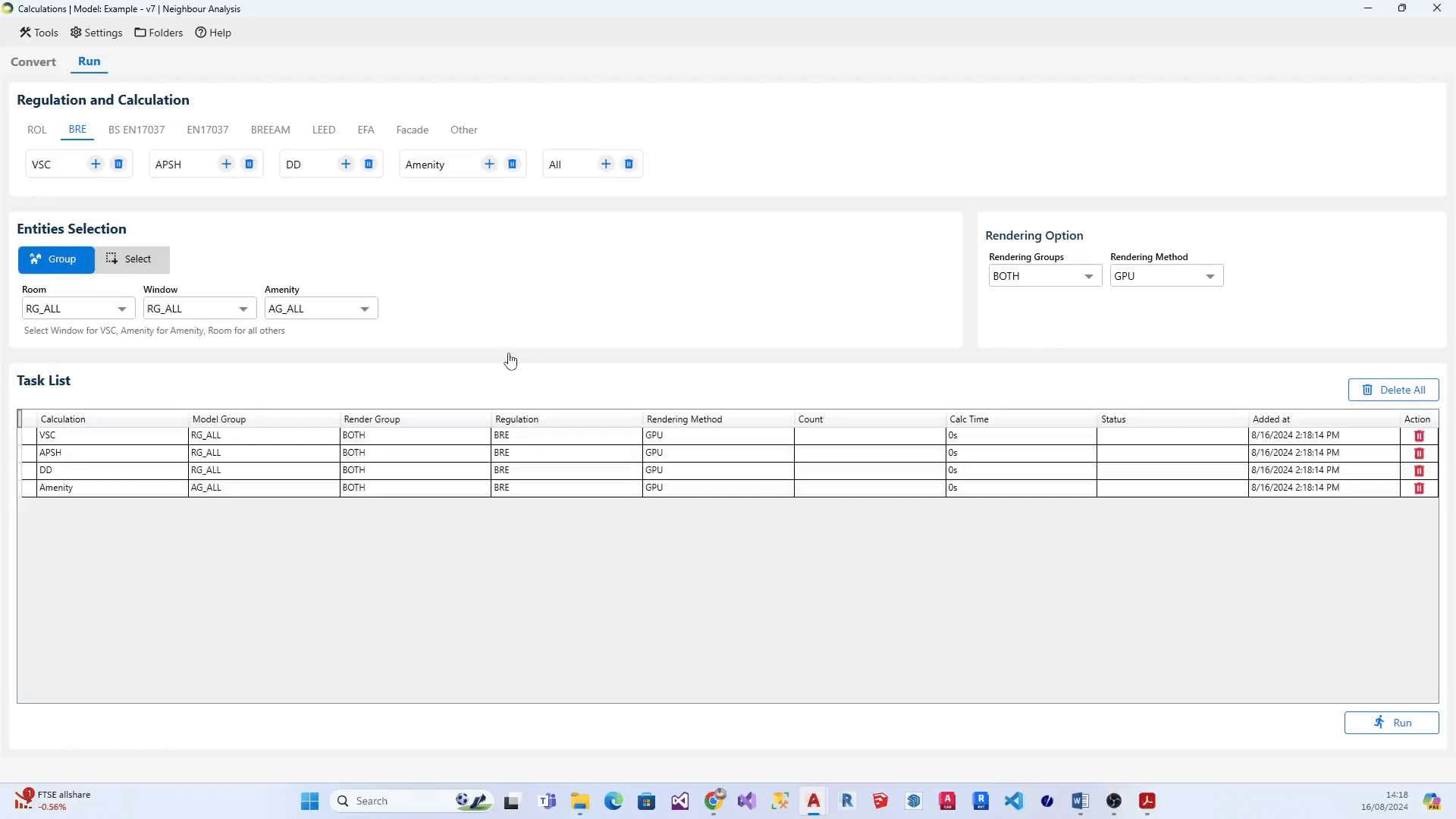
What are the steps to add calculations to the list?
- Select the relevant regulation (eg: ROL, BRE, BS EN17037). The associated calculations get displayed below each regulation.
- Set the Group on the relevant boxes.
- Click on the + icon next to the calculation name to add the individual calculation.
- Alternatively, Click on the + icon next to All to add all the calculations in the regulation.
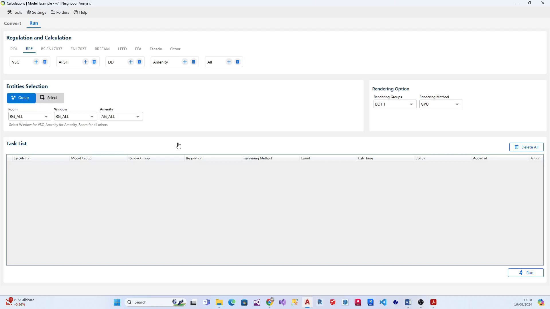
What are the steps to add multiple groups for a calculation to the list?
- Select the relevant regulation (eg: ROL, BRE, BS EN17037). The associated calculations get displayed below each regulation.
- On Enitities Selection section, Select All option from the relevant entity (i.e. Room, Window, Amenity, Facade). Note: All option will be displayed only if there is more than one group in that particular entity type.
- After selecting the All option, click on + icon next to the desired calculation. Alternatively, you can click + icon next to All calculations if you would like to add all the groups for the calculations in the regulation to the task list.
What are the steps to modify group for calculation on the list?
- Head to the relevant task on the task list and right-click on it.
- A little popout dialogue containing the list of relevant groups for the selected calculation will appear on your screen.
- Select the required group and click on Save.
What unit is used by the software?
- Metres.
- If the model is in millimetres, registration and conversion process would take forever and/or give errors.
- Model must be scaled to metres.
No Contour is created after running ROL/DD Calculation
- Use DrawRoomGridPoints to check calculation points position. They should be located in the WP height.
If not update the room (this is usually the case if the room is moved/rotated/reshaped without being updated). - Check if the window is facing inside, it must face outside. Use SpinWindows command to fix.
- Convert the model if windows have been updated but the model has not been converted again.
- View the model in Conceptual mode and check if any entities block the window.
- Use DrawRoomTriangles command to check the triangulation. If it gives error, then the problem may be the room is not registered properly.
Can PROPOSED group be created automatically when doing ROL cutbacks?
- Yes.
- Tick the Auto create PROPOSED group option in Asset tab.
- It will re create the group from objects in 3D_PROPOSED_BUILDINGS layer.
What transparency value should be used for Waldram image?
- Transparency: 0 = When overlapping, Proposed on top, Existing Hidden
- Transparency: 255 = When overlapping, Existing on top, Proposed Hidden
- Transparency :155 (or anything in middle) = Both visible
What does the colour of the dot indicate in APSH Waldram diagram?
- Dark Blue dot indicates winter sun
- Dark Yellow dot indicates summer sun
- light Blue dot indicates blocked winter sun
- light yellow dot indicates blocked summer sun
- Dot with hole indicate that the dot is seen by more than one window.
What does the colour of the dot indicate in SE Waldram diagram?
- Dark Yellow dot indicates sun dot visible from the window.
- Light yellow dot indicates sun dot blocked for the window.
- Red dot indicates that the dot is seen by more than one window in the room.
Do I need to Assign Material for registered Windows?
- No.
- Any registered windows will automatically get ThinGlass material (or glass in Radiance format).
- Therefore it is not required to create records for them in Material Table.
What happens to registered Windows Glazing Transmittance?
Any registered windows will automatically get ThinGlass material(or glass in Radiance format). Therefore it is not required to create records for them in Material Table. The material requires normal incidence transmittance for its definition which is derived from the ADF properties of the window at the registration time.
Td: Diffuse Transmittance (is used in BRE ADF formula)
Tn: Normal Incidence Transmittance
According to BRE Appendix C:
“diffuse transmittance can be found by multiplying the manufacturer’s normal incidence light transmittance by 0.91”
Tn = (Td ÷ 0.91)
And from BS8206 15.2:
“If daylight factors are calculated from the overall aperture area in the wall or roof, instead of the net glazed area, a further correction factor should be used. If there are any other obstructions, such as curtains or structural supports, the overall transmittance should be reduced in proportion to the area of opening that they obscure.”
T = Tn × GM × MF
T is the value used to derive parameters required for definition of glass material on any ray-tracing based Climate and Daylight Factor calculation.
GM: Frame Factor
MF: Maintenance Factor
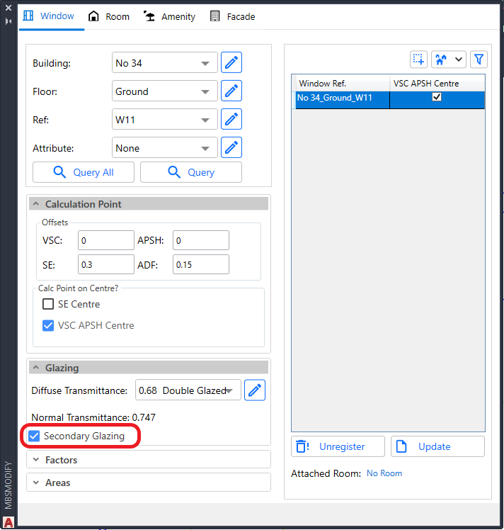
When to use Secondary Glazing option on Windows?
- This is an option which can be assigned to Windows during Registration or Update.
- This option is targeted for VSC and ADF calculations.
- Useful to analyse windows behind transparent balconies and winter garden.
- The windows in winter garden and transparent balcony can be registered as Secondary Glazing in order to reduce the inside window result by the relevant transparency of the outside window.
- For VSC and ADF calculations,
- If the outside windows are registered as normal windows, they will be treated as fully transparent by the inside window and thus not reducing the result by the relevant transparency.
- For ADF calculation,
- They don’t need to be/should not be attached to the Room when running ADF calculation.
- If they are attached to the room, they will be automatically ignored when calculating the room ADF to avoid overestimating the value.
- For ROL/DD calculations,
- The Secondary Glazing windows are ignored as if they are fully transparent.
- This is to avoid the need for them to be removed from the groups when running ROL/DD calculations.
- Because registered windows which are not attached to the room being calculated will be treated as opaque surface by ROL/DD calculations.
- It is also possible to calculate VSC for the Secondary Glazing Windows.
- The alternative is to assign ThinGlass material to the balcony surfaces using MBS material dialog.
- Refer to How to assign the Materials for Balconies? topic under Material Settings knowledge page.
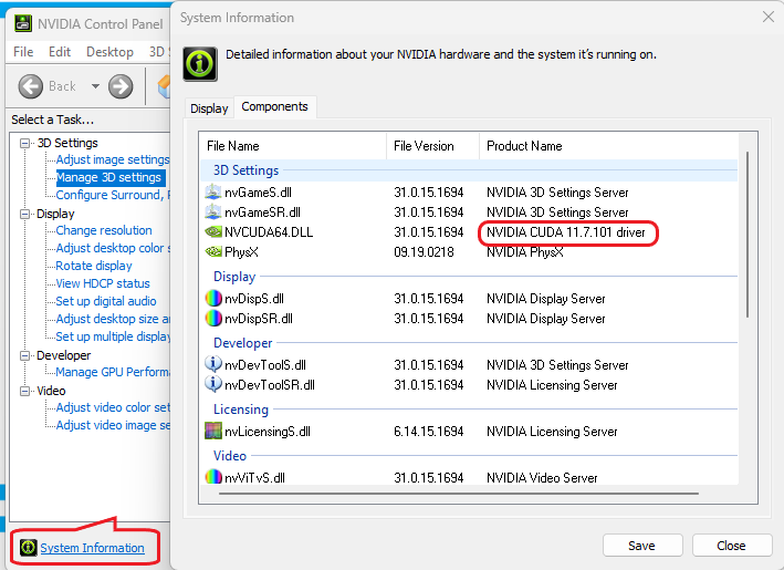
Which Graphics Card is required for GPU Calculation?
- The GPU calculation requires a compatible Nvidia graphics card.
- The Nvidia card must have compute capability of 3.5 or higher.
- This can be checked on this NVIDIA site
- https://developer.nvidia.com/cuda-gpus#compute
- Some older version supported cards are listed here https://developer.nvidia.com/cuda-legacy-gpus
- The Nvidia card must support CUDA driver version 11.1 or higher
- The computer must have CUDA driver version 11.1 or higher installed
- This can be checked by opening NVIDIA control panel (Right click on Desktop)
- Click on System Information and then Click on the Components Tab
- If the CUDA driver version is lower than 11.1, it can be upgraded by using the NVIDIA GeForce Application.
- If it is not installed on the computer, it can be downloaded from this NVIDIA site https://www.nvidia.com/en-gb/geforce/geforce-experience/
- Open Nvdia GeForce Experience
- Log in or Create Account
- Click on Drivers then Check for Updates
Daylight Factor
BREEAM Daylight Factor Criteria
Terms and Definitions
Average Daylight Factor
The average daylight factor is the average indoor illuminance (from daylight) on the working plane within a room,
expressed as a percentage of the simultaneous outdoor illuminance on a horizontal plane under an unobstructed CIE Standard Overcast Sky.
Point Daylight Factor
A point daylight factor is the ratio between the illuminance (from daylight) at a specific point on the working plane within a room, expressed as a percentage of the illuminance received on an outdoor unobstructed horizontal plane. The minimum point daylight factor is the lowest value of the daylight factor on the working plane at a point that is not within 0.5m of a wall.
Uniformity
The uniformity is the ratio between the minimum illuminance (from daylight) on the working plane within a room (or minimum daylight factor) and the average illuminance (from daylight) on the same working plane (or average daylight factor).
Daylight Factor Criteria
BREEAM 2018
The relevant building areas must meet
1. Minimum value of average daylight factors required
2. Daylighting uniformity criteria
BS EN17037 Daylight Factor Criteria
Daylight Factor Criteria
UK National Annex
The UK Annex is intended for “hard to light” dwellings.
The targets for DF is linked to the lux targets defined for BS EN17037 SDA (This can be accessed via Project Settings Climate Daylighting tab). The target DF is calculated based on the target illuminance and the median external diffuse illuminance. e.g. For London Gatwick, median illuminance is 14100. The equivalent target DF for 100 lux is (100 / 14100) % 100 % i.e. 0.7%
The target DF is to be met for 50% of the time over 50% of the space
EN17037 Daylight Factor Criteria
Daylight Factor Criteria
The targets for DF is linked to the lux targets defined for EN17037 SDA. (This can be accessed via Project Settings Climate Daylighting tab). The target DF is calculated based on the target illuminance and the median external diffuse illuminance. e.g. For London Gatwick, median illuminance is 14100. The equivalent target DF for 300 lux is (300 / 14100) % 100 % i.e. 2.1%
The target DF is to be met for 50% of the time over 50% of the space. The min target DF is to be met for 50% of the time over 95% of the space.
Setting Pass Criteria
Assessment Criteria are set per project in Project Settings dialogue > Climate Daylighting tab.
Select the regulation first and then Press the … button next to the regulation to open the Climate Criteria dialog for the regulation.
DF BS EN17037 Criteria
The criteria is set according to BS EN17037 regulation. The DF criteria are derived from the SDA criteria based on the room type and the Median diffuse horizontal illuminance for the location.
For e.g. Median diffuse horizontal illuminance for London Gatwick based on the energy plus epw file is 14100. So the equivalent DF target for Living Room will be (150/14100)*100 = 1.1
DF EN17037 Criteria
The criteria is set according to EN17037 regulation. The DF criteria are derived from the SDA criteria based on the selected space type targets and the Median diffuse horizontal illuminance for the location.
For e.g. Median diffuse horizontal illuminance for London Gatwick based on the energy plus epw file is 14100. So the equivalent DF target for 300 Lux will be (300/14100)*100 = 2.1
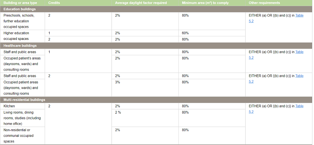
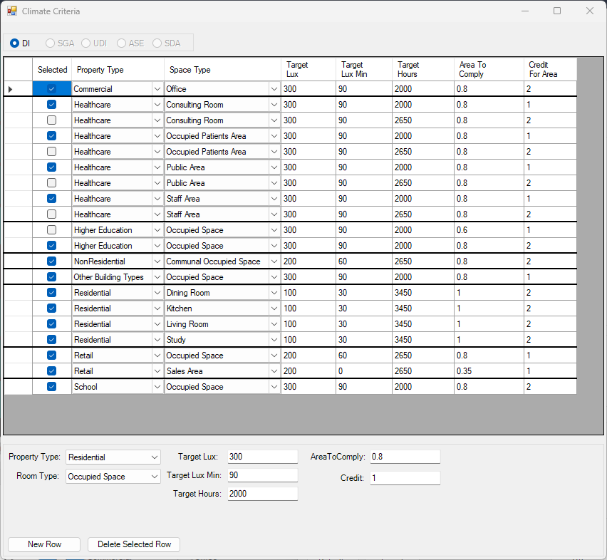
BREEAM DF Criteria
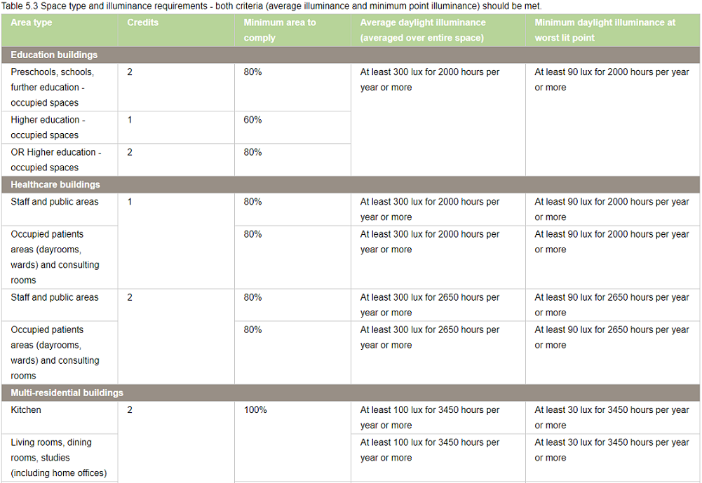
All the entries on BREEAM Regulations Table 5.1 are predefined based on the BREEAM New Construction 2018 and loaded as default in Criteria table dialogue.
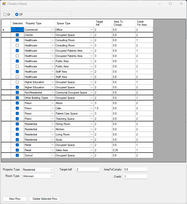
Each property and room type pair in BREEAM Regulations Table 5.1 is translated into one or two rows(based on number of credits, target lux, occupied hours) in the dialogue.
If a property, room type pair has different credits or target DF, one row is added for each credit in the table dialog.
For example, Higher education occupied space can achieve 1 credit with 60% area with 2% and 2 credits with 80% area with 2%
Two records are added to the table with the corresponding values for credit value and target DF.
The first entry for higher credit is selected for calculation.
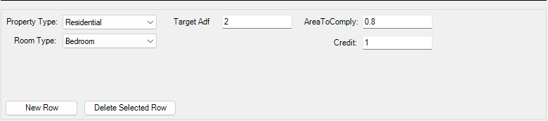
– To Delete an existing criterion select the row on the table and press the Delete Selected Row button.

To Add new criterion fill in the text boxes with corresponding criterion and press the New Row button. Note that the AreaToComply column takes value between 0 – 1.
– To Update an existing criterion simply change the values on the table.
The Selected column displays the criteria that are set for calculation. The DF calculation uses the
registered property and space type of a room to query its assessment criteria from the above table. If more than one records exists for this property and room type, the Selected is returned from the table. If no records exists the default “Other Building Types” and Occupied Space criterion is used.
Notes for All DF Criteria
Note 1: The output report displays criteria that has been set prior to running the calculation.
In other words the selected criteria record is saved against the room on calculation time and same criteria is queried at report time.
Note 2: Changing the Selected criteria, changes to Target DF, Target DF Min requires re-running the calculation.
“Area To Comply” and “Credit For Area To Comply” does not require rerun.
Steps to run Daylight Factor Calculation
- Put the objects in the model in specific layers. e.g. walls in “wall” layer, any external obstructions in “external” layer and so on.
- The registered windows will automatically get Glass material based on their properties set during the registration time.
However the registered windows must be added to relevant group before conversion.
For more details on how to setup the model for running Daylight Factor, utility commands that automate the process and questions on Window Glazing Transmittance,
please refer to the topic How to prepare a model for Assigning the Materials? in Materials knowledge base section. - Open the Material dialog and assign a material for each layer. Material Library has a predefined list of most of the common materials. Yet you can define your own or customize them.
For more details on how the material dialogue works please refer to the About Material Dialog topic in Materials knowledge base section. - Set the Ray tracing Method and its options on Application Settings > Calculation tab > Ray Tracing section.
- The Sky distribution used for Daylight Factor is CIE Overcast Sky. However this can be changed to Uniform Sky on Project Settings dialogue > Calculation tab for experimental purpose.
- Tick Convert to Radiance format or Convert to GPU format before Converting the model.
- Set climate regulation to BREEAM, BS EN17037 or EN17037
- Finally run the calculation using the CPU or GPU rendering method
Climate Based Calculations
BS EN17037 Illuminance (SDA) Criteria
Illuminance Criteria
UK National Annex
The UK Annex is intended for “hard to light” dwellings.
The illuminance targets for BS EN17037 SDA can be accessed via Project Settings Climate Daylighting tab.
The target Lux is to be met for 50% of the time over 50% of the space.
Notes (Also Applies to EN17037 Criteria too)
- Daylight Hours: The hours of daylight are determined by rank-ordering (i.e. from highest to lowest) the 8760 values for diffuse horizontal illuminance and then extracting the first (i.e. the highest) 4380 hourly values. Note that the retained (i.e. highest) 4380 values may include some zero values, or that the discarded 4380 values may include some non-zero values.
This is to be expected given the nature of illuminance data in climate files and does not affect the outcome. - The relevant area of the space plane covers the entire space, and is located 0.85m above the floor.
- A perimeter area is excluded from the area of the space, because locally, illuminances are not relevant to the assessment of daylight provision, since the illuminances can be excessively high (near windows) or excessively low, next to opaque walls. A perimeter area is the area located next to the walls of the space, and should be excluded in daylight calculations.
EN17037 Illuminance (SDA) Criteria
Illuminance Criteria
The illuminance targets for BS EN17037 SDA can be accessed via Project Settings Climate Daylighting tab.
For spaces with daylight openings in vertical and inclined surface, The target Lux is to be met for 50% of the time over 50% of the space. The min target Lux is to be met for 50% of the time over 95% of the space.
For spaces with daylight openings in horizontal surface, The target Lux is to be met for 50% of the time over 95% of the space. There is no minimum target lux.
BREEAM Illuminance (DI) Criteria
Terms and Definitions
Average daylight Illuminance
Daylight illuminance for all points in the space for a specific hour (e.g. 1st Jan 8 AM) is averaged. If this average is over the target lux (e.g. 300 lux) value, the hour will count towards the achieved hour for the target lux.
Minimum Daylight Illuminance
The lowest point daylight illuminance in the space at a specific hour e.g. 1st Jan 8 AM) on the working plane within a room. The minimum point daylight factor is the lowest value of the daylight factor on the working plane at a point that is not within 0.5m of a wall. If this lowest lux value is over the target lux min value (e.g. 90 lux), the hour will count towards the achieved hour for the target lux min.
Setting Weather Location and Hours
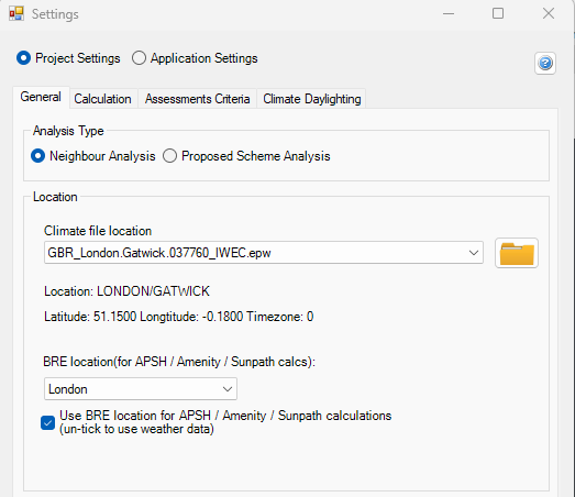
Setting up Weather data and Location
Select location for climate based calculation on Project Settings dialogue > General tab > Location section. All weather data files must be in epw format and located in below folder:
Autocad: %appdata%/MBS Software/DaylightForAutocad/Climate Files
Revit: %appdata%/MBS Software/DaylightForRevit/Climate Files
For new locations, the .epw file (IWEC format) can be downloaded from the energy plus website.
- Select the region then the country then the location and then select epw to download the file.
- Once downloaded copy the .epw file to the above appdata folder which can be opened by clicking the Folder icon next to the climate file location combo box.
This setting is project specific and needs to be set per job.
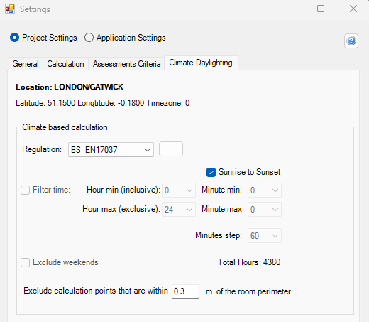
Setting up Climate Hours
- Before running the calculation, the regulation and annual daylight hours options have to be set through Project Settings > Climate Daylighting tab.
- The test has to be run separately for each regulation. Results are saved per regulation and thus once they are calculated, corresponding reports could be outputted without a re-run.
- The recommended daylight hours for BREEAM, BS EN17037and EN17037 is Sunrise to Sunset.
- For BS EN17037 and EN17037, 50% of the hours with the highest illuminance (4380 hours) is used instead of all the hours between sunrise and sunset.
- The filter hour is inclusive for the start hour and exclusive for the end hour.
For example, if the occupancy starts at 9 AM and finishes at 5PM, the filter hour should be set to 9 to 17 (8 Hour Occupancy)
Setting Pass Criteria
Assessment Criteria are set per project in Project Settings dialogue > Climate Daylighting tab.
Select the regulation first and then Press the … button next to the regulation to open the Climate Criteria dialog for the regulation.
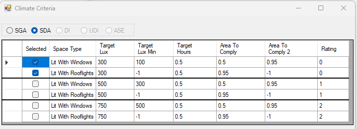
SDA BS EN17037 Criteria
The criteria is set according to BS EN17037 regulation. The criteria are set based on the space type.
SDA EN17037 Criteria
The criteria is set according to EN17037 Regulation. The criteria are fixed and grouped by their rating. The Selected criterion is queried and used for calculation.
BREEAM DI Criteria
All the entries on BREEAM Regulations Table 5.3 are predefined based on the BREEAM New Construction 2018 and loaded as default in Criteria table dialogue.
Each property and room type pair in BREEAM Regulations Table 5.3 is translated into one or two rows(based on number of credits, target lux, occupied hours) in the dialogue.
If a property, room type pair has different credits, target lux or occupied hours one row is added for each credit in the table dialogue.
As an example, below Staff room type in Healthcare property has two entries for 1 Credit and 2 Credit with different occupied hours.
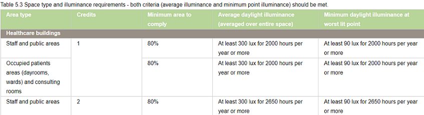
Two records are added to the table with the corresponding values for credit value, target lux and occupied hours.
The first entry for credit 1 is selected for calculation.
– To Delete an existing criterion select the row on the table and press the Delete Selected Row button.

To Add new criterion fill in the text boxes with corresponding criterion and press the New Row button. Note that the AreaToComply column takes value between 0 – 1.
– To Update an existing criterion simply change the values on the table.
The Selected column displays the criteria that are set for calculation. The DI calculation uses the
registered property and space type of a room to query its assessment criteria from the above table. If more than
one records exists for this property and room type, the Selected is returned from the table. If no records exists
the default “Other Building Types” criterion is used.
Notes for All Climate Criteria
Note 1: The output report displays criteria that has been set prior to running the calculation.
In other words the selected criteria record is saved against the room on calculation time and same criteria is queried at report time.
Note 2: Changing the Selected criteria, changes to Target Lux, Target Lux Min, Target Hours requires re-running the calculation.
“Area To Comply” and “Credit For Area To Comply” does not require rerun.
Steps to run Climate-Based Calculation
- Put the objects in the model in specific layers. e.g. walls in “wall” layer, any external obstructions in “external” layer and so on.
- The registered windows will automatically get Glass material based on their properties set during the registration time.
However the registered windows must be added to relevant group before conversion.
For more details on how to setup the model for running Daylight Factor, utility commands that automate the process and questions on Window Glazing Transmittance,
please refer to How to Setup a model for Assigning the Material? topic in Materials knowledge base section. - Open the Material dialogue and assign a material for each layer. Material Library has a predefined list of most of the common materials. Yet you can define your own or customize them. For more details on how the material dialogue works please refer to About Material Dialog topic in Materials knowledge base section.
- Set the Ray tracing Method and its options on Settings > Ray tracing method
- Tick Convert to Radiance format or Convert to GPU format before Converting the model.
- Set climate regulation to BREEAM, BS EN17037 or EN17037 or LEED or EFA
- Select SDA or DI calculation
- Finally run the calculation using the CPU or GPU rendering method
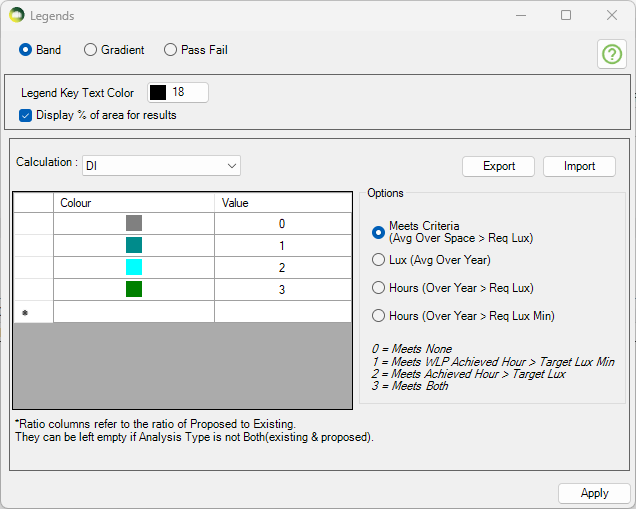
BREEAM DI Results
The DI results can be presented visually in 4 different ways.
- As shown in the image, the Meets criteria option will show a single colour image for the room based on whether Achieved hour > Target Lux and/or Worst lit point achieved hour > Target Lux Min are met or not.
- Please note that the rest of the three options are alternative presentation of the result and do not show the achieved hour for target lux and target lux min as averaged over the space
- The Lux (Avg Over Year) option can be used to show the average lux achieved by each point in the room over the year.
- Hours (Over Year > Req Lux) option can be used to show the number of hours when each point in the room achieve the req lux.
- Hours (Over Year > Req Lux Min) option can be used to show the number of hours when each point in the room achieve the req lux min.
The DI Excel result contains the results for the main criteria as well as some alternative results.
As shown in the DI criteria results image,
- The Req Lux Achieved Hours column shows the total number of hours when lux value averaged over the space is at least 300 Lux.
- The WLP Achieved Hours column shows the total number of hours when the worst lit point lux value (except foe the points within 0.5m of the wall) is at least 90 Lux.
- The Meets Criteria column shows Yes, If both Req Lux Achieved Hours and WLP Achieved Hours are more than the 2000 hours (Req hour per year).
The Alternative result columns are to the right of the Meets criteria column and are added to give alternative results for each points over the year.
- The Avg Annual Lux column shows the average lux value based on the average lux achieved by all the points in the room. Each points average lux value can be shown by using the Lux (Over the year) option in Legend settings.
- The % of Area Meeting Req Lux column shows the percent of the points which have an average of at least 300 Lux.
- The Avg Annual Achieved Hours column shows the average achieved hours value based on the achieved hours with at least 300 lux achieved by all the points in the room. Each points achieved hours with at least 300 lux can be shown by using the Hours (Over Year > Req Lux) option in Legend settings.
- The % of Area Meeting Req Hours column shows the percent of the points which achieve 2000 hours with at least 300 Lux.
- The Avg Annual WLP Achieved Hours column shows the average achieved hours value based on the achieved hours with at least 90 lux achieved by all points in the room. Each points achieved hours with at least 90 lux can be shown by using the Hours (Over Year > Req Lux Min) option in Legend settings.
- The % of Area Meeting Req Hours (WLP) column shows the percent of the points which achieve 2000 hours with at least 90 Lux.
BREEAM V7 Calculations
Daylight Illuminance (DI)
BREEAM Illuminance (DI) Criteria
Terms and Definitions
Average daylight Illuminance
Daylight illuminance for all points in the space for a specific hour (e.g. 1st Jan 8 AM) is averaged. If this average is over the target lux (e.g. 300 lux) value, the hour will count towards the achieved hour for the target lux.
Minimum Daylight Illuminance
The lowest point daylight illuminance in the space at a specific hour e.g. 1st Jan 8 AM) on the working plane within a room. The minimum point daylight factor is the lowest value of the daylight factor on the working plane at a point that is not within 0.5m of a wall. If this lowest lux value is over the target lux min value (e.g. 90 lux), the hour will count towards the achieved hour for the target lux min.
BREEAM DI Results
The DI results can be presented visually in 4 different ways.
- As shown in the image, the Meets criteria option will show a single colour image for the room based on whether Achieved hour > Target Lux and/or Worst lit point achieved hour > Target Lux Min are met or not.
- Please note that the rest of the three options are alternative presentation of the result and do not show the achieved hour for target lux and target lux min as averaged over the space
- The Lux (Avg Over Year) option can be used to show the average lux achieved by each point in the room over the year.
- Hours (Over Year > Req Lux) option can be used to show the number of hours when each point in the room achieve the req lux.
- Hours (Over Year > Req Lux Min) option can be used to show the number of hours when each point in the room achieve the req lux min.
The DI Excel result contains the results for the main criteria as well as some alternative results.
As shown in the DI criteria results image,
- The Req Lux Achieved Hours column shows the total number of hours when lux value averaged over the space is at least 300 Lux.
- The WLP Achieved Hours column shows the total number of hours when the worst lit point lux value (except foe the points within 0.5m of the wall) is at least 90 Lux.
- The Meets Criteria column shows Yes, If both Req Lux Achieved Hours and WLP Achieved Hours are more than the 2000 hours (Req hour per year).
The Alternative result columns are to the right of the Meets criteria column and are added to give alternative results for each points over the year.
- The Avg Annual Lux column shows the average lux value based on the average lux achieved by all the points in the room. Each points average lux value can be shown by using the Lux (Over the year) option in Legend settings.
- The % of Area Meeting Req Lux column shows the percent of the points which have an average of at least 300 Lux.
- The Avg Annual Achieved Hours column shows the average achieved hours value based on the achieved hours with at least 300 lux achieved by all the points in the room. Each points achieved hours with at least 300 lux can be shown by using the Hours (Over Year > Req Lux) option in Legend settings.
- The % of Area Meeting Req Hours column shows the percent of the points which achieve 2000 hours with at least 300 Lux.
- The Avg Annual WLP Achieved Hours column shows the average achieved hours value based on the achieved hours with at least 90 lux achieved by all points in the room. Each points achieved hours with at least 90 lux can be shown by using the Hours (Over Year > Req Lux Min) option in Legend settings.
- The % of Area Meeting Req Hours (WLP) column shows the percent of the points which achieve 2000 hours with at least 90 Lux.
Spatial Daylight Autonomy (SDA)
The Spatial Daylight Autonomy (sDA) calculation is based on the EN 17037 methodology for daylight assessment, in accordance with BREEAM guidance. For further details, please refer to GUIDANCE NOTE 50, Section 1.3.
BREEAM Recommendation
The EN 17037 gives three levels of recommendation for daylight provision in interior spaces: minimum, medium and high.
- To meet the standard credits, a space only need to reach the minimum level.
- To qualify for the Exemplary credits, the space must reach the high level.
In both cases, the required minimum area that meets daylight levels depends on the building type and must meet in accordance with the standard and exemplary level credits.
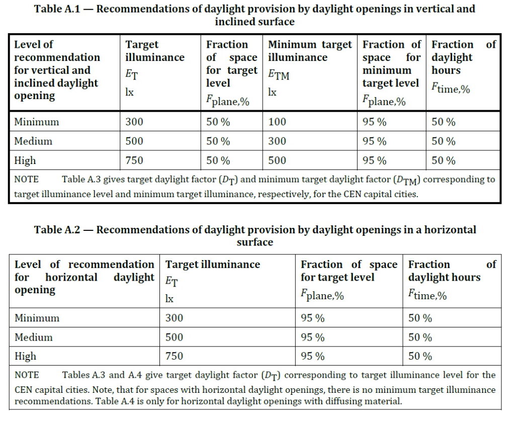
For rooms that receive daylight from windows or sloping openings, enough light should reach the working area (the reference plane) for at least half of the year’s daylight hours. Specifically:
- A main brightness target (ET) should be met in at least half of the space.
- A lower minimum brightness level (ETM) should be met almost everywhere — at least 95% of the space.
Following table shows the exact light levels for window-lit rooms. A space is considered well-lit if it meets both the main brightness target (ET) and the minimum brightness target (ETM).
| Level of recommendation | Target illuminance ET (lx) for half of reference plane | Minimum target illuminance ETM (lx) for 95% of reference plane |
| Minimum | 300 | 100 |
| Medium | 500 | 300 |
| High | 750 | 500 |
For rooms lit from above (such as skylights or roof openings), the main brightness target (ET) should be met in almost the entire working area — at least 95% of the space — for at least half of the year’s daylight hours. Following table shows the required light levels for these top-lit spaces. Unlike window-lit rooms, there is no additional minimum brightness requirement (ETM).
| Level of recommendation | Target illuminance ET (lx) for 95% of reference plane |
| Minimum | 300 |
| Medium | 500 |
| High | 750 |
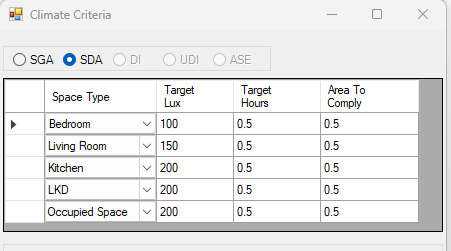
Setting up Assessment Criteria
- Open the Settings dialog.
- Select the Climate Daylight tab.
- In the Climate-Based Calculation section, set the regulation to EN 17037.
- Click on … (options) and choose SDA Calculation.
- Select the Targets values as needed:
- For standard credit select the row with 300 lux.
- For exemplary credit select the row with 750 lux.
- If needed, update the target values and other criteria to match your project requirements.
Sunlight Exposure (SE)
BREEAM Recommendation
Each relevant units* must have at least one area that gets 3 or more hours of direct sunlight on equinox days (21 March or 21 September) under clear skies.
Reference Points for Calculation
- For windows – reference point must be the inside face, at the centre of the window width, and at least 1.2 m above the floor or 0.3 m above the sill (whichever is higher).
- For rooflights – reference point must be the geometrical centre of the opening on the inside face.
*A relevant unit would be a distinct building or space intended for single residential-like occupancy type. Where units are self-contained, such as a house or flat each self-contained unit must be considered separately. Where there are shared communal areas such as in a residential care home, then the whole care home can be considered one relevant unit. In a healthcare scenario, a healthcare ward that overnight patients have direct access to would be considered one unit.
Setting up Assessment Criteria
- Open the Settings dialog.
- Select the Climate Daylight tab.
Spatial Glare Autonomy (SGA)
SGA is an annual DGP calcualtion (Daylight Glare Probability).
BREEAM Recommendation
| Glare protection level | DGPe<5% | BREEAM exemplary glare performance |
| Minimum | 0.45 | No |
| Medium | 0.40 | Yes |
| High | 0.35 | Yes |
Limitation of Software
The software runs the SGA calculation for the entire room. To determine whether individual workstations meet the exemplary level criteria, the user must either perform a manual calculation using the grid point results or register each workstation as a separate room.
Setting up Assessment Criteria
- Open the Settings dialog.
- Select the Climate Daylight tab.
- In the Climate-Based Calculation section, set the regulation to EN 17037.
- Click on … (options) and choose SGA Calculation.
- Select the Targets values as needed:
- For example select Target DGP 0.4 to meet BREEAM medium Glare protection level.
- If needed, update the target values and other criteria to match your project requirements.
Annual Sunlight Exposure (ASE)
BREEAM Recommendation
Annual Sunlight Exposure (ASE₁₀₀₀,₂₅₀ ≤ 10%)
No more than 10% of the occupied floor area in relevant building spaces may receive a daylight illuminance of ≥ 1000 lux for ≥ 250 hours per year.
Setting up Assessment Criteria
- Open the Settings dialog.
- Select the Climate Daylight tab.
- In the Climate-Based Calculation section, set the regulation to LEED.
- Click on … (options) and choose ASE Calculation.
- If needed, update the Target Lux, Target Hours and Area to Comply to match your project requirements.
Default annual occupancy hours can be taken to be 8am to 6pm local clock time on Monday to Friday. This parameter can be modified by unticking the Sunrise to Sunset Option in Climate based calculation section.
ASE occupancy hours
View out
BREEAM Recommendation
At least 75% of the floor area in 95% of relevant spaces must meet both of the following criteria:
- A horizontal sight angle of 28° or greater.
- A view that includes the landscape layer and at least one other layer (sky or ground) through a permanent opening.
Setting up Assessment Criteria
- Open the Settings dialog.
- Select the Assessment Criteria tab.
- In the View section.
- If needed, update the target values and other criteria to match your project requirements.
- The target % of area required to meet criteria is taken from % of Utilized Area. This value must be 75% to meet BREEAM recommendation.
- Target % of relevant space required to meet is taken from Target % of Spaces In a Building section. This value must be 95% to meet BREEAM recommendation.
- A horizontal sight angle value is taken from Medium field of Horizontal Sight Angle section.
View Out Assessment Criteria
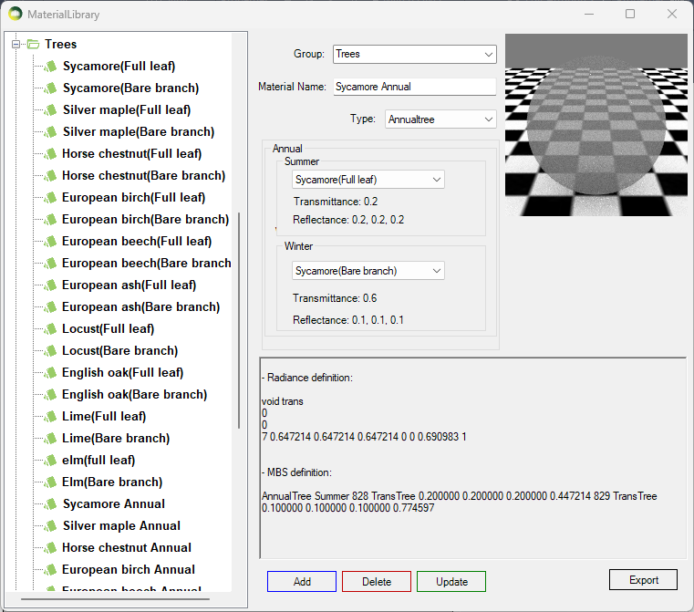
SDA Calculation With Trees
In order to include Trees in the SDA annual calculation, the new Annualtree material should be used. It combines the existing TransTree material to specify Summer and Winter materials for trees. The dates for Summer and Winter trees is specified in Project Settings > Climate Daylighting. This is a special material for SDA calculation and should not be used with any other calculations.
e.g. if the Annualtree material is used with Summer Start Date 21 March and Winter Start Date 21 September then the SDA calculation is run once for the Summer date e.g. 21 March to 20 September using the Summer tree material and once for the Winter date e.g. 21 September to 20 March using the Winter tree material. The results are then combined to give an overall annual result.
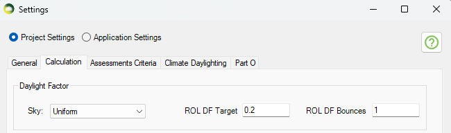
ROL DF
ROL DF Calculation
This calculation is to test for ROL by including reflected light using the Daylight Factor method.
In order to match the Waldram method, the default target is set to 0.2 and the default bounce is set to 1 (Direct light only). The Sky should be changed to Uniform in the same place. The default Daylight factor sky is set to Overcast. The windows attached to the room should be taken out of the group before conversion in order to avoid reducing the result by the window transmittance value as the waldram method doesn’t include windows during the calculation
These values can be changed in Project Settings > Calculation tab > Daylight Factor section.
The Legend settings can be changed under ROL DF on the Legends Dialog.
Sunlight Exposure
Minimum recommendation
This is to be checked in the reference point at the centre of the window width and at the
inner surface of the aperture (façade and/or roof). For multiple apertures in different façades it is possible to cumulate the time of sunlight availability if not occurring at the same time. The reference point is minimum 1.2 m above the floor and 0.3 m above the window sill (whichever is higher).
NOTE 1 To allow flexibility for rooms orientation the angle of window normal αwn,s = 120° measured from South and the minimum sun height γs,min are applied. Solar altitudes below those stated in Table D.1 (BS EN17037 guide) are neglected in the evaluation.
Minimum recommendation for exposure to sunlight
The minimum recommendation is that the room should receive possible sunlight for a duration higher than 1.5 hours (supposed to be cloudless) on March 21.
Table A.5 proposes three levels for exposure to sunlight.
| Recommendation | Sunlight Exposure (Hours) |
| Minimum Exposure | >= 1.5 |
| Medium Exposure | >= 3.0 |
| High Exposure | > 4.0 |
Table A.5
Run calculation
The test date can be changed on Project Settings > Climate Daylighting tab.
The default date is set for March 21.
Open Run dialogue and select Sunlight Exposure to run the calculation.
Glare Analysis
Annual Potential Glare
Specular material that reflects Sun beam directed towards the view point is detected
as glare source and is marked in colour banding on the image.
Steps to create the Annual Potential Glare image and report
1. Set the location in Project Settings > General tab by selecting the weather file.
2. Assign specular material (ThinGlass, Mirror, Metal and Plastic) in Material dialogue to all surfaces that are considered to be potential for reflecting glare. All registered windows are
automatically applied ThinGlass material and no material definition is needed in the material dialog.
3. Open the Render dialogue. Select the view point and direction either by entering the
coordinates or picking them from the model by pressing the button next to the input boxes.
4. Select Potential Glare option
5. Change Camera type to Fisheye and set the view angle accordingly.
The view angle for fisheye is between 0 to 180.
6. Optionally change the driver’s age. Default age is set to 65 to give the worst case result.
7. Display Hours option can be ticked to show the time on the image. If the Display hour every is set to Zero, then only the hour texts are shown e.g. 08:00 or 09:00.
If the Display hour every set to non zero value e.g. 15, then the hour and minute for the interval will be shown e.g. 08:15 or 08:30. This option can cause the image creation to take longer for smaller minute intervals.
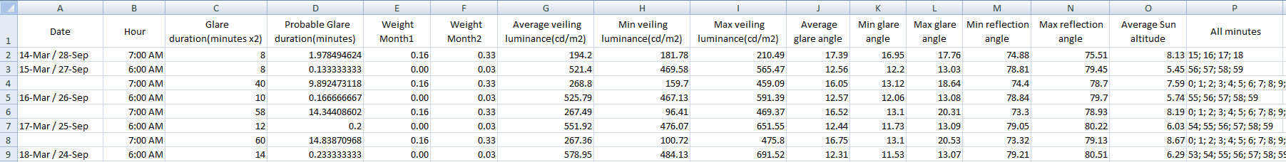
8. Tick “Create Report” option to generate csv report for the rendered image.
The report contains information for every pixel that has glare occurrence.
This includes date and time, glare intensity in cd/m2, distance from the glare, field of view angle of the glare.
The report and images are saved in the [Model_Name]_Waldram/Images/GlareTest folder.
9. Start the Subpixel sample with at least 50 and Increase it by 25 to render a sharp image. The noise in the image is inversely proportional to the square root of this number. The image on the right is rendered with 50 subpixel samples and is little bit blurry so it should be rendered with higher subpixel samples.
10. Press Render button.
Understanding the image output
- Circles
- The circles in the image represent 10 degree steps except the first and sometimes the last step.
- The image on the right side is created using a view angle of 60 degrees. The inner most red circle is a special one added to represent the 3 degrees of view angle (6 degree in total which is affected the most). The next three lines are for 10, 20 and 30 on each side and thus totalling the 60.
- If the view angle is not a multiple of 20, then the last one will be the half of the view angle. e.g. if the view angle of 70 is used, then the circle lines will be for 3, 10, 20, 30 and 35.
- Colours
- The colours in the glazed surfaces represent the colours for the month when the potential glare occurs.
- A legend with the month name and the colours can be added to the rendered image by going to Render dialogue options > General tab and ticking Add header to the image option.
Glare DGP
For the assessment of daylight glare EN17037 please refer to the annual potential glare.
This is a point-in-time calculation. Radiance evalglare program is used to calculate DGP value.
According to En17037 glare is defined as:
“Condition of vision in which there is discomfort or a reduction in the ability to see details
or objects caused by an unsuitbale distribution or range of illuminance, or by extreme
contrasts.“
DGP is defined as:
“the probability that a person is disturbed instead of the glare magnitude as a glare
measure. This new probability function is called daylight glare probability, DGP“.
It is an approach to consider both illuminance at eye level and individual glare sources of high luminance to estimate the fraction of dissatisfied persons.
According to En17037:
“DGP can be applied to any daylight oriented indoor space which is mainly side-lit and where the expected tasks are comparable to office tasks.“
| Criterion | Daylight Glare Probability(DGP) |
| Glare is mostly not-perceived | DGP <= 0.35 |
| Glare is perceived but mostly not disturbing | 0.35 < DGP <= 0.40 |
| Glare is perceived and often disturbing | 0.4 < DGP <= 0.45 |
| Glare is perceived and mostly intolerable | DGP >= 0.45 |
Steps to render an image for DGP calculation
- Set the climate file location Project Settings > General tab
- Set the Raytracing method to Radiance in Application Settings > Ray tracing tab
- Set the Sky to clear CIE sky type Settings > Ray tracing tab.
Note: changes to sky type requires model re-conversion for Radiance option. - As this is a point-in-time calculation, location, date and time have to be set in advance via Render dialog Options > General tab (Click on the … button on the render dialog to open the options).
- The default Glare DGP threshold is 7 and it can be changed in Render dialog options > Glare tab.
-
Based on the provided threshold either of the two methods are used for detection of glare sources:
-
Method A: Calculate the average luminance of the entire picture and count every section as a glare source that is x-times higher than the average luminance. For this method try values less than 100: this factor multiplied by the average luminance in the entire picture will be used as threshold for detecting glare sources.
-
Method B. Take a fixed value and count every section as a glare source that is higher than the fixed value. For this method try values over 100: the value is used as
-
- Select a view point either by providing the coordinates on the input box or picking a point within the room (working plane).
- The camera type automatically is set to Fisheye. Set the field of view angle as required.
- Set the desired image quality and press Render. The yellow areas on the image displays the glare sources.
-
DGP value along with other glare metrics are calculated and saved in a text file in the [Model_Name]_Waldram/Images/GlareTest folder.
EN17037:
Testing position should be either a current used position of a person(workplace or often used position) or a position, which might be used and which might have a glare problem.
Such positions are usually close to the facade and/or facing facade orientations.
The viewing direction of the measurement devices should face towards the facade parallel to the floor and towards the azimuth direction of the sun. The height of the view point should be in 1.2m height.
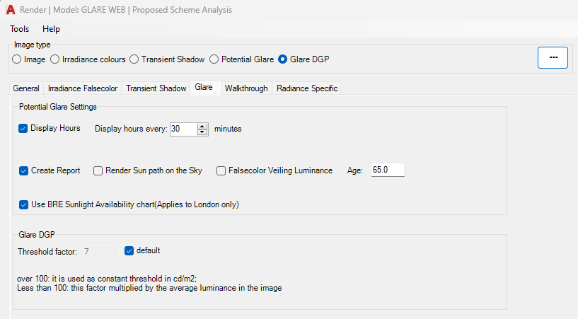
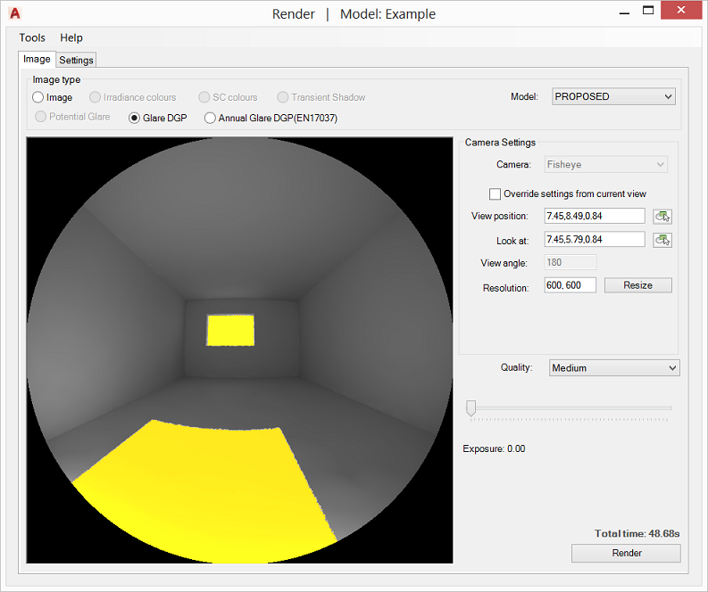
Rendering
Transient Shadow Analysis
Objects in Proposed and Existing group would cast shadows same colour as their material colour. Transient Shadow Test image can be rendered using CPU or the GPU.
- Open the Application Settings > Calculation tab and choose the desired Rendering method. (GPU render require a compatible NVIDIA graphics card)
- Specify location by selecting the corresponding climate file location in Project Settings > General tab
- Open the Render dialog options > Transient Shadow tab and set the required test start and end time.
- Set the required interval (in minutes).
- The individual equinox dates can be easily set by selecting the desired date from the combo box.
- The Run All Dates option can be ticked to run for three dates 21 March, 21 June and 21 December in one Render. The times are in GMT.
- In Image tab select Shadow Test and pick the model group from the box.
- Set Camera mode to Perspective.
- Camera position and look At can be set in two ways: A. Either tick the “Override settings from current view” to setup the camera to the current view or a predefined camera. This option works better in AutoCAD Perspective mode. B. Press the View Position box button to select the position from the model. Repeat the process for Look At.
- Horizontal field of view is set via View Angle box. The effect is similar to zoom in or out.
- The image box can be resized manually through resizing the dialogue or by setting the desired resolution in Resolution box and pressing the resize button.
The resolution can also be manually be set to a value bigger than the display screen. - Set pixel samples number and press Render. The noise is inversely proportional to square root of this number: four times more samples are required to decrease the error by half.
- The shadow images are saved in the [Model_Name]_Waldram/Images/ShadowTest folder. Image file name will include the day, month and the time. No image is created for the times where the sun is not present e.g. after the sunset.
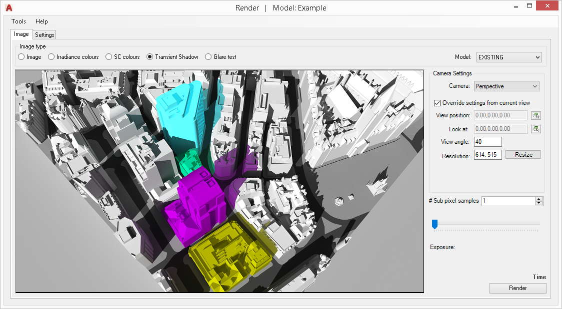
A background texture image can be set by inserting a Raster image into the model. Make sure the image belongs to either of the analysis groups.
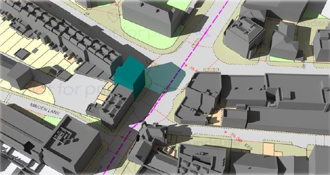
Tick the New Shadow Only option to exclude part of the coloured shadow that already is rendered under the existing scenario.
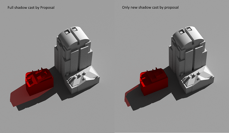
Normal Image
- Open the Render dialogue
- Specify location by selecting the corresponding climate file in Project Settings > General tab.
- Pick Radiance or PathTracing from the Render dialog options > General tab > Raytracing Method combo box.
- Also Set sky type, date and time on the same tab.
-
Select Existing or Proposed model from the Model box.
-
Camera position and look At can be set in two ways: A. Either tick the Override settings from current view to setup the camera to AutoCAD current view. This option works better in AutoCAD Perspective mode. B. Or press the View Position box button to select the position from the model. Repeat the process for Look At.
-
Horizontal field of view is set via View Angle box. The effect is similar to zoom in or out
- The image box can be resized manually through resizing the dialogue or by setting the desired resolution in Resolution box and pressing the resize button. The resolution can also be manually be set to a value bigger than the display screen.
- Set pixel samples number and press Render. The noise is inversely proportional to square root of this number: four times more samples are required to decrease the error by half.
Optional Settings under the Options > General tab:
- Picture box image can display the progress by ticking the “Show Progress” option.
- Tick Interactive rendering to pan / orbit the rendered image within the picture box. Hold left mouse button down to pan the image. Hold right mouse button down to rotate the image.
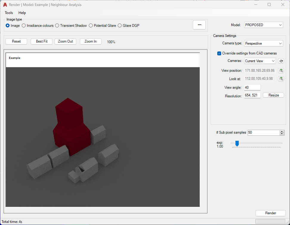
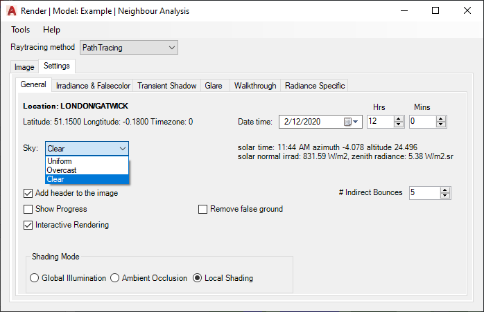
Shading Modes
There are three Shading mode supported in Path tracing mode:
- Global Illumination which produces unbiased path-traced simulation of light paths. This is the default mode.
- Ambient Occlusion option accounts only for the visiblity term. A cosine-weighted visibility factor calculated for the hemisphere of a surface point. An example is demonstrated here.
- Local Shading mode quicken the rendering but removing diffuse inter-reflection from calculation. Phong-shading model is used to render materials with pre-defined three directional lights.
Irradiance and Sky Component image
The process is same as described for rendering normal images. The maximum range of legend colours is set in Render dialog Options > Irradiance and Falsecolor tab.
The minimum is always set to zero. The maximum value can be set and is interpreted as follow:
- Values between 0 to 100 is used as Daylight Factor or Sky Component ratio.
- Values above 100 are taken as absolute lux value.
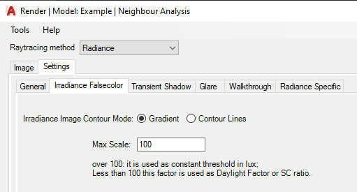
If Radiance is selected as the rendering method, two false color image modes are provided:
– Gradient option produces smooth interpolation between values on the image.
– If contour lines are desired rather than just false color image, the Contour Lines option can be used. These lines are placed over the normal Radiance picture rather than falsecolor image.
– Contour Bands produces contour bands instead of lines, where the thickness of the bands is related to the rate of change in the image.
Note:
Radiance falsecolor image uses pre-defined Radiance pm3d colour palette with 8 colours.
The image on the side shows daylight factor gradient image with corresponding values set in legend, for an indoor scene.
An hdr file format is saved along the png format, loaded through Tools > Load hdr image, which can be used to display the image with different legend colours without re-rendering the image.
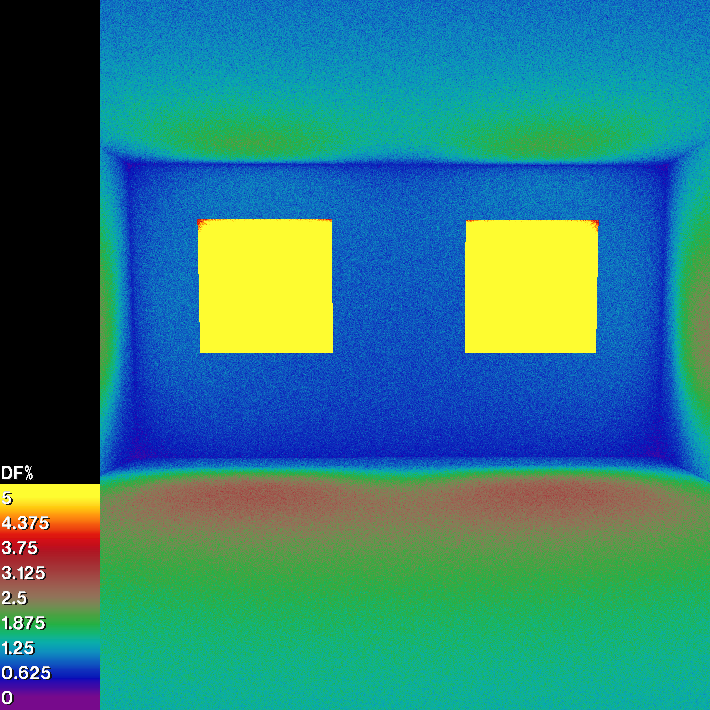
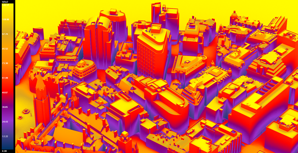
Render FAQs
Rendered image is too bright. Most objects in the image are washed out and are not visible.
Adjust the exposure using the slider in Render dialogue. This linearly changes the image brightness. if the image is too bright or too dark, the level of the brightness can be adjusted
by changing the exposure level through the slider.
In Path tracing mode the slider updates the image immediately without a need to render the image.
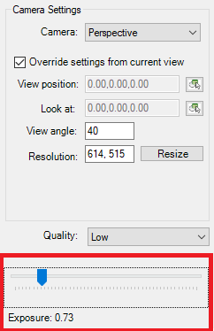
In Radiance mode, the exposure takes effect after rendering it image again.
Alternatively you may tick “Open Radiance image with wxfalsecolor” option in Render dialog options > General tab to open the Radiance image in wxfalsecolor application to set the exposure directly. This immediately updates the image without re-run.
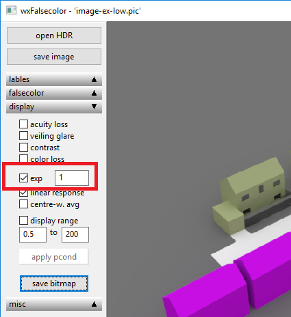
Facade Analysis
Registration Steps
- Open the Register Dialogue by clicking
 icon from menu bar or by typing MBSRegister command.
 - Go to Facade Tab
- Enter the Grid Spacing and select Highlight Facade Colour (Selected
objects are highlighted using this colour) as per your requirement. - Type name for facade in Facade Name field. Alternatively, you can enable the auto name option from settings which will add the facade name automatically.
- Auto Naming option can be enabled/disabled from Register section in Application Settings. Similary, you can also set your own custom prefix to be used for facade name.
- Facade mapping can be done for
- 3d solids, Regions and closed 2d Polylines.
- 3d solid faces
- Polyface, Polygon mesh and 3D faces.
- Select the appropriate Selection option.
- Select the objects.
- Select button can be used multiple times to add objects in different parts of the model. Text message next to select and register bottom shows the total objects which are selected which should also be highlighted using the Highlight Facade colour. Button next to text messsage can be used to clear selected facade before registration.
- Click on Register.
- It is possible to create a classicgroup with objects supported for Facade registration (group name must start with FG_ ). The group then appears in the Selection list.
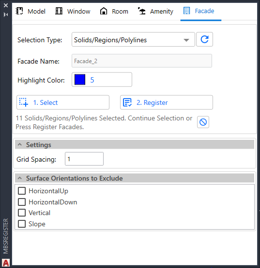
Modify Steps
- Open the Modify Dialogue by clicking
 icon from menu bar or by typing MBSModify command.
 - Go to Facade Tab.
From modify dialog, you can add / remove faces, rename facade, update grid spacing and unregister the selected facades.
Note: If the recently registered facade is not shown in the table, click on the Reload button above the table, which will repopulate the table.
Add Face
- Click on the + icon in the table. This will show a new section called edit below the Grid Spacing section.
- Choose the type of object you want to select from the model in the Selection Type option.
- Click 1. Select.
- Select the relevant face you want to add. After selection, the selected count gets displayed as a text message below the buttons.
- Next, click on 2. Add Faces. This will append the selected faces with existing faces.
Remove Face
- Click on the – icon in the table. This will show a new section called edit below the Grid Spacing section.
- Choose the type of object you want to select from the model in the Selection Type option.
- Click 1. Select.
- Select the relevant face you want to remove. After selection, the selected count gets displayed as a text message below the buttons.
- Next, click on 2. Remove Faces. This will detach the selected faces from the facade.
Rename Facade
- Click on icon. This will show a new section called Rename.
- Enter the desired name you want to give for the selected facade in Facade Name field.
- Click on Rename button. This will update the name of selected facade in table.
Upgrade Grid Spacing
- Select the Facades from the table. (You can select multiple facades at once.)
- Enter the desired Grid Spacing in the Grid Spacing field.
- Click the Update Grid button. The Total Point column gets updated once the grid point update is complete.
Unregister Facade
- Select facades in the the table. (You can select multiple facades at once.)
- Click on Unregister Facade button.
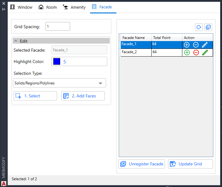
Calculation Steps
- Go to the Calculation dialogue (MBSCalculation command) and convert the model groups by clicking the Convert button at the bottom right in the Convert tab.
- Go to Run tab.
- Under the Regulation and Calculation section, click on the Facade Tab. All the supported calculations for Facades are listed under this tab.
- Select the calculation type by clicking on the tick box and change the Facade Name from the dropdown box displayed in the Entities Selection section if required.
- All option from the Facade dropdown can be used to add all the registered facades in one go for selected calculation.
- Before running, make sure the settings are right.
- Open Legends dialogue, you can select either Gradient or Bands.
- To get results on legend select “Display % of area for results” option. See Legend Settings Section for more details.
- After changing the Settings, click on OK.
- Open Application Settings > Calculations tab, enter Sky sub division angle for VSC calculation (5 degree is suggested).
- Click the Run button at the bottom right in the calculations dialogue to run the calculation.
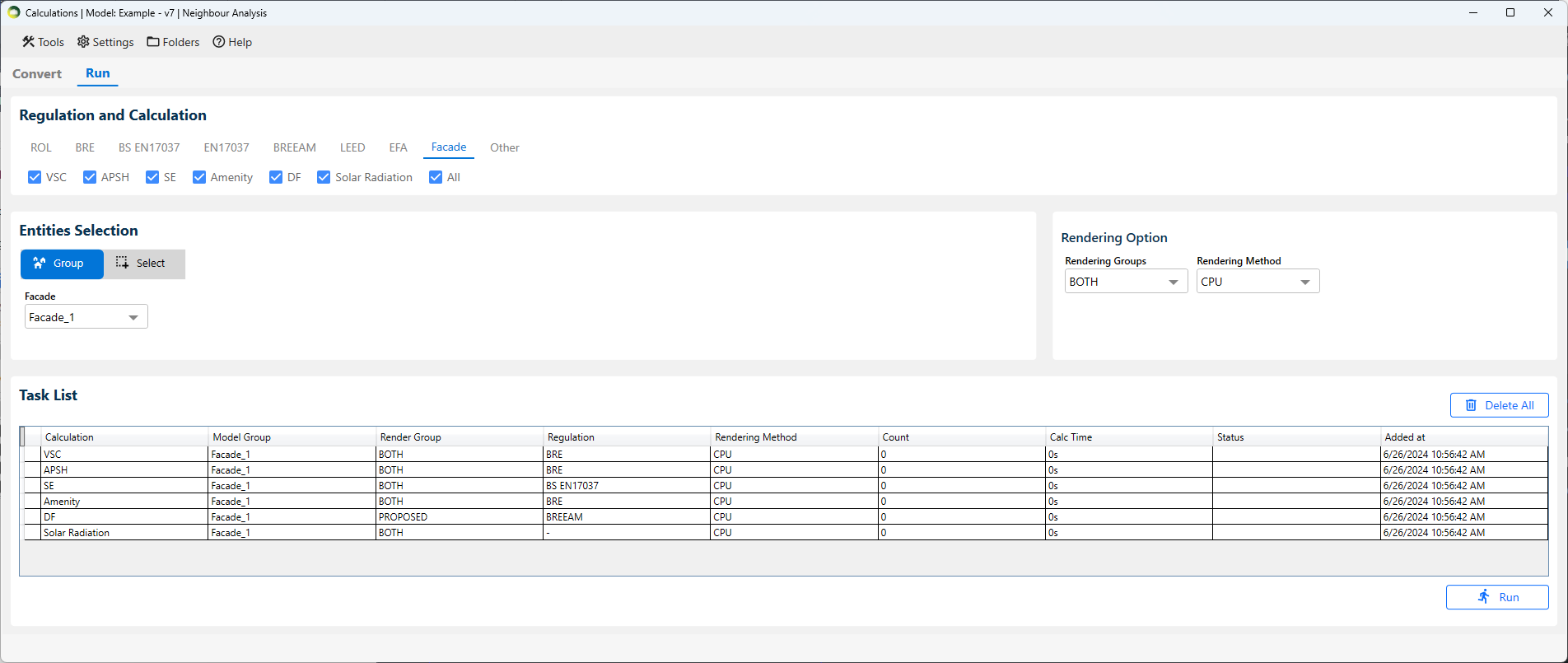
Result Steps
- Each calculation has its own layer (ex: FACADE_1_VSC_PROPOSED_FACADE).
- If you select “both” groups you also get the loss (ratio of proposed and existing) in its own layer (ex: FACADE_1_VSC_LOSS_FACADE).
- Use Realistic/Shaded visual style as mesh colours are not visible in Wireframe view.
- The facade legend can be found in [Model_Name]_Waldram\images\FacadeLegend folder. The image on the right is created for VSC Proposed using Gradient mode.
- CSV report are automatically created in [Model_Name]_Waldram\Reports folder.
Clear Facade Result
- Open Calculation dialogue.
- Click on Tools in menu bar.
- Click on Clear results > Facade Results.
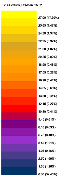
Façade FAQs
Why are Mesh colours not seen in Autocad?
- Mesh objects are visible by layer colour in Wireframe view.
- Change view to Realistic/Shaded to see the individual Mesh face colours.
- To see Mesh face colours in Wireframe view, explode the Mesh so that it gives faces whose colours can be seen in any view.
Solar Radiation
Solar Radiation
Solar Radiation can be run as a Facade calculation, the model must be converted to Radiance and thus requires Radiance to be installed on the computer.
The test date can be changed on Project Settings > Climate Daylighting tab. The default date is set for 01 Jan to 31 Dec
- This is a an annual cumulative Solar radiation calculation.
- The final output is given in KWh/m2
- The calculation is based on the epw climate file.
- The calculation includes direct contribution from the sun on cloudy condition (as per the climate file) and also includes the contribution from the atmosphere.
- A legend image and CSV report are created during the calculation.
- The CSV report includes values for all the ranges that are defined in the Legends settings. The default is set to 0 to 1000 Kwh/m2
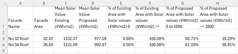
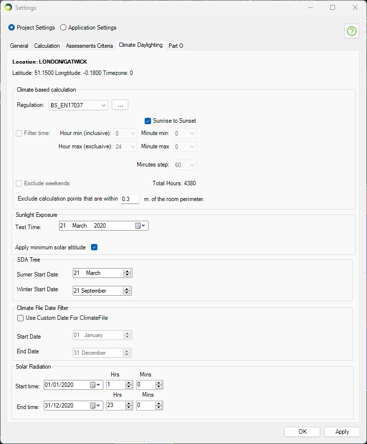
Spatial Glare Autonomy
Spatial Glare Autonomy (SGA)
- This is an annual DGP calculation (Daylight Glare Probability).
- DGP is calculated against a threshold of 0.45. This can be changed in Project Settings > Climate Daylighting > EN17037 Criteria.
- Each grid point in the room will have multiple view points (6 by default). This can be changed in Project Settings . Climate Daylighting > Annual DGP views per point.
- The visual result as shown in the image shows the % of time each view point exceeds the threshold of 0.45
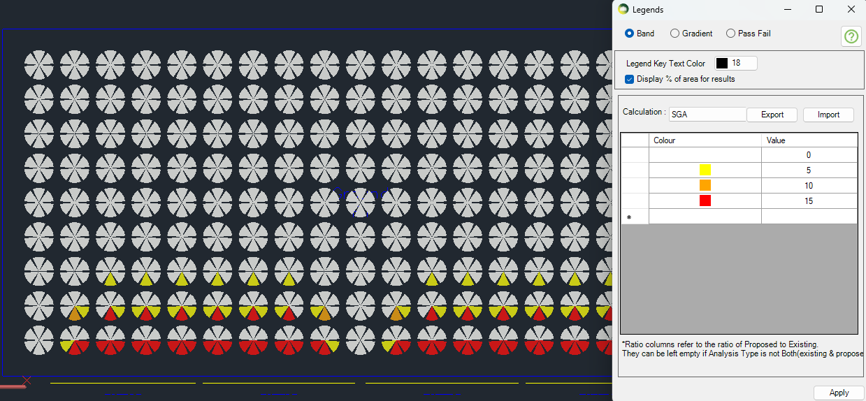
Excel Report
- SGA Pr % of views column shows the total % of the view points which are exceeding the req % of hours.
- If the view’s DGP is more than 5% target, it will be counted towards the PR % of SGA for the room e.g. SGA Pr % of view 10 % means that 10% of 1026 points (102 points) exceed the 0.45 DGP for at least 5% of the time.
- Avg DGPs column shows the Average Percent of time the DGP is more than the target for the room. (Average of Average DGP for each point)
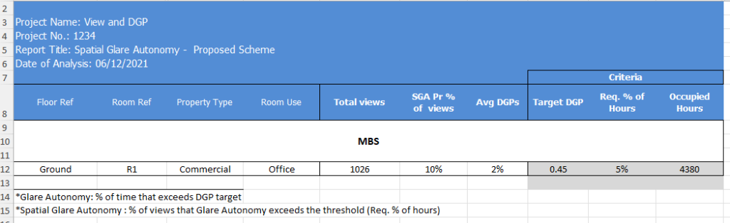
View Calculation
View out criteria
View to the outside provides visual contact with the surrounding, so as to supply information for orientation, to experience the weather changes and to follow with the time over the day.
The view quality depends on
- the size of the windows and the distance from the reference point to the window which together gives width of the view,
- the outside distance of the view (distance from the inner surface of view opening to opposite major obstructions located in front of the opening)
- the number of layers and
- the quality of the environmental information of the view.
According to EN17037:
- “The criteria for view out concerns the utilized area” section 5.2.2
- “View to the outside should be assessed from selected reference points corresponding to where people are located within the utilize area”. section 5.2.1.
- “Three levels of view out, horizontal sight angle, the distance to outside view, and the number of layers are assessed from reference positions.” section A.3
And regarding the required % of the utilized area for Horizontal Sight Angle and Distance Out C.3 states that
The reference points can be at any potential location within the utilized area of the space.
Implying that 100% of the utilized area is required for the criterion to pass. This parameter can be set to a different value within the software. Refer to the below section on where to set this.
The Criteria for Minimum View Out:
- View Windows should have minimum dimensions (Width x Height = 1m x 1.25 m)
- For all reference points on the utilized area, Distance to Outside elements should be larger than minimum value (6 m)
- For all reference points on the utilized area, view windows should have a Horizontal Sight Angle higher than the minimum value (14 °)
- A minimum fraction (75%) of the utilized area, the users of the space should be able to see at least the landscape layer.
Indicative points of the projection should be at points in the room where people are actually sitting (eyelevel 1.2 m over the floor) or standing (eyelevel 1.7 m over the floor).
View out assessment
Assessment of the view outwards from a given position
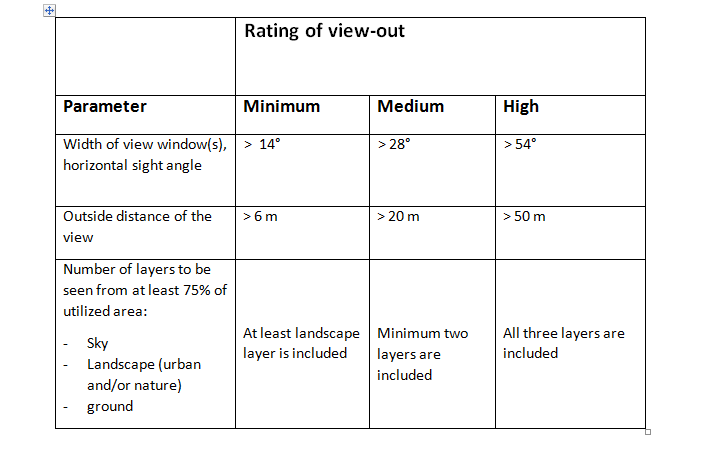
Outside Distance is calculated across the utilized area for each reference point. The rating is done as follow for each reference point:
The averaged distances to the outside obstructions are calculated for each of the three bands (minimum, medium, high) separately. It is the average of all distances to the outside obstructions that fall within a specific radius(correspond to the band). This is considered as valid only if the obstructions within the band obscure the view more than a specified threshold (e.g. 10% threshold in above figure). Otherwise the band is regarded as having no obstructed view and no shortest distance is recorded.
A full sphere fisheye view is rendered for each reference point to accumulate distances on each band from all the openings.
The Settings for View calculation can be set from Project Settings > Assessment Criteria tab:
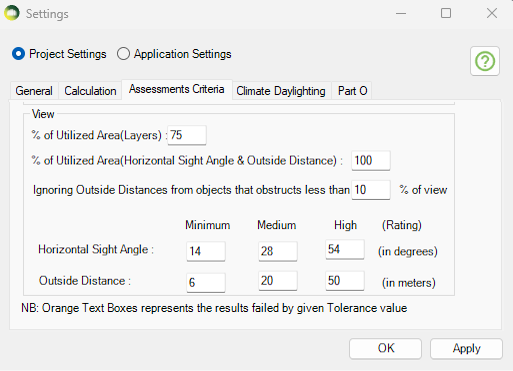
The ViewTest dialog (MBSViewTest command) can be used to visualize the three tests.
The image on the right shows outside distances from a point inside a room. The outside distance is calculated across the utilized area for each reference point. The rating is done as follow for each reference point:
- Distances to landscape layer is used. Distance to Sky and Ground are not used for outside distance to view.
- The average distances to the outside obstructions are calculated for each of the three bands (minimum, medium, high) separately.
- It is the average of all distances to the outside obstructions that fall within a specific radius (correspond to the band).
- This is considered as valid only if the obstructions within the band obscure the view more than a specified threshold (e.g. 10% threshold in above figure). Otherwise the band is regarded as having no obstructed view and no shortest distance is recorded.
- For example, In the image shown, the shortest distance to view is taken from the 0–<6 band as the % of view in that is more than the 10% threshold. If the % of view is less than 10% then the shortest distance will be checked in the 6- < 20 band and so on.
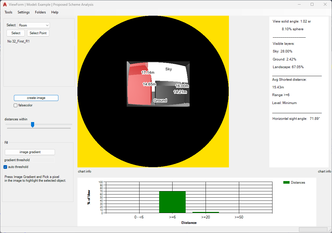
The image on the right shows the falsecolor map for distance to view and other visible layers. Sky, Ground, Inside Room, Beyond lens and various distance band are allocated various colors to distinguish the objects seen from the reference point.
The percentage of visible layers seen (Sky, Ground and Landscape) are shown on the right hand side. The average shortest distance and horizontal sight angle are shown as well.
The chart shows the % of view taken by distance to view in each band.
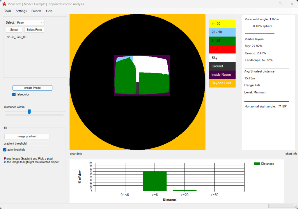
Report FAQs
What are the steps to Preview the results?
- Open preview dialogue (MBSPreview command in AutoCAD).
- Click on the relevant Regulation tab and select the calculation.
- In the Entities Selection section, choose the relevant group or select the entities (Room/Window/Amentity) from the model you are interested in.
- Next, click Preview.
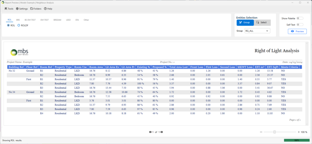
What are the steps to Export the results?
- Open Export dialog (MBSExport command in AutoCAD).
- Click on the relevant regulation.
- Select the tick boxes next to the calculation name to be exported.
- Use a Group from the dropdown or Select entities whose results need to be exported.
- VSC and APSH results are exported in the same sheet for the (default) report and use the VSC group. Bespoke reports may vary.
- Click Export CSV or Export Excel based on your requirements.
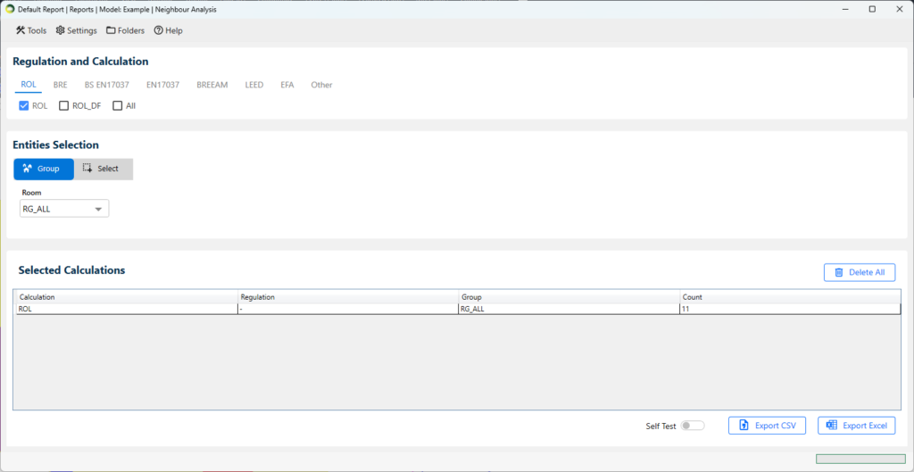
How to use tags from Project Settings in Excel Reports?
- Replaceable tags can be inserted in Excel template including header and footer.
- They should be specified as <tag> e.g. <Project Name> <Report Title>.
- The values can be defined in Project Settings dialog.
Label FAQs
What are the steps to add results to the label?
- Select entity type Window/Room/Amenity
- Tick Existing, Proposed or both options as necessary
- Select the result to be added VSC/APSH/ADF/DD/ROL
- FOR DF and SDA, select one or both Show Median or Show Area % options
- Tick Show Failures option to highlight the failed results with red coloured labels
- Click on Add Labels to add/update labels
Commands for Autocad
Dialog Commands
- MBSRegister Opens the Register dialog. This dialog can be used to Register rooms, windows, amenities and facade
- MBSModify Opens the Modify dialog. This dialog can be used to Query and Update registered rooms, windows, amenities and facade
- MBSCalculation Opens the Calculation dialog. This dialog can be used to Convert the model and to Run various calculations.
- MBSPreview Opens the Report Preview dialog. This dialog can be used to Preview various calculation results.
- MBSExport Opens the Report Export dialog. This dialog can be used to various calculation results in CSV and Excel formats.
- MBSLabel Opens the Label dialog. This dialog can be used to add and modify reference labels, results and solids to rooms, windows and amenities.
- MBSRenderGpu Opens the GPU Render dialog. This requires a compatible Nvidia Graphics card. This dialog can be used to render images, transient shadow and falsecolor image for Sky Component and Daylight Factor.
- MBSRenderCpu Opens the CPU Render dialog. This dialog can be used to render images, transient shadow and to run potential glare and glare dgp tests.
- MBSCutback Opens the Cutback dialog. This dialog can be used to facilitate a cutback.
- MBSViewTest Opens the view out assessment dialog. This dialog can be used to visualise view out tests.
- MBSSettings Opens the combined Project and Application Settings dialog.
- MBSLegends Opens the Legends dialog
- MBSMaterial Opens the Material dialog
All dialogs consist of menu to access general settings, project specific settings and software version information.
Scripts for dialogs
- MBSConvert Script to convert Groups. This command can be used to quickly convert the groups
- CalculationScript Script to run calculations from saved scripts. This command can be used to quickly run calculation if it is being run repeatedly. The script can be saved locally or
in a shared folder. - ExportScript Script to export Excel or CSV reports from saved scripts. This command can be used to quickly export results. The script can only be saved locally.
Utility Commands
- MBSInfo Command to show basic information about registered Room or Window. This command shows Room id, attached windows or Window id, attached room and setting values and calculation results
SubtractCutback Command to manually subtract Cutback objects from Proposed solids. Subtracted objects are put in CutbackInterference layer - SkyScanner Command to visualize the irradiance and sky component calculation from centre of the window
- SunAPSH Command to visualize APSH calculation from the centre of the window.
- HrSC Command to calculate ROL and DD for a given set of points under uniform and CIE overcast sky
- CalcIrrad Command to calculate daylight factor for given points. Settings are taken from Settings dialogue.
- CreateSectionLayers Command to create layers required for Sections. Default suffox is “Plans”. User can also provide custom Suffix.
This command can be used to automatically create layers for section. Layers will be created in the format of BuildingName_FloorName_Plans for all floors of all buildings in the model. User can change the _Plans suffix if needed. It also creates a layer property filter named plans
Error Fixing Commands
- SpinWindows Command to display Window normals and fix inside facing windows.This command can be used to rotate windows, which are facing towards the room, by 180 degrees to make them face away
from the room. - SlopeWindows Command to display Window which are inclined below certain angle and to remove the inclination.This command can be used to remove inclination from windows which are accidently inclined by few degrees.
- CExtDic Command to fix corrupted extension dictionary for windowsThis command is useful for example if waldram images are created but no results appear on report.
- CopyLinkW2R Command to fix Room to Window linkThis command can be used to fix Room-window link when Window-Room link is correct but Room-Window link is broken.
Debugging Commands
- MBSVersion Command to show current version of Waldram Tools Software.
This command shows Waldram Tools version, Company Code and last update date. - MBSJobFolder Command to open waldram job folder for the active model
This folder contains the exported report files, images, backup results, log file and model specific settings. - MBSConfigFolder Command to open waldram config/settings folder for the current user
This folder contains user specific settings, master copies of model specific settings, report templates and other software related files. - MBSLogFile Command to open the waldram log file for the active model
The log file contains debug information and error log related to the model. - DrawRoomGridPoints Command to draw grid points for rooms
This command can be used to draw grid points used for the calculation of contours. It is useful to check the grid points are in correct location in the model when the contour doesn’t appear after running calculation. - DrawAmenityGridPoints Command to draw grid points for amenities
This command can be used to draw grid points used for the calculation of contours. It is useful to check the grid points are in correct location in the model when the contour doesn’t appear after running calculation. - DrawModelGrid Command to draw grid points for the whole model
This command can be used to draw grid structure of the whole model created by the conversion process. - DrawRoomTri Command to draw triangles for rooms
This command can be used to draw triangles used for the calculation of contours. - DrawAmntTri Command to draw triangles for amenities
This command can be used to draw triangles used for the calculation of contours. - DrawModelTri Command to draw triangles for the whole model
This command can be used to draw triangles created by the conversion process. - MinBB Command to draw minimum bounding box for windows
- MBSTrace Command to visualize Raytracing and material behaviour
- NoResults Command to highlight entities with 0 or no result
Highlighting Room Interior Surfaces
The ExtractRoomSurfaces command is a utility command in AutoCAD that automatically extracts floors, walls and ceilings and put them in corresponding layers.
- Make sure rooms and windows are registered for the building that you want to assign material.
- Type the command name in command bar and press Enter.
- It asks to “select buildings, rooms and windows”. Select the building, together with all the rooms and windows on this building and press Enter
- Once the command is done, three layers “walls”, “floors” and “ceilings” in different colors are created which contains all corresponding objects.
Know issues and limitations with this command:
- any type of object is supported including solid, 3d face or mesh
- as it uses ray-casting approach to detect surfaces, it assumes the model has already been converted through the Run dialogue.
- assumes the model is light tied. That is internal walls between rooms, floors and ceilings do exist in the model. It does not create any walls or ceilings.
- A single object can only get one material for both back and front face. Therefore if there is no wall thickness, the object will go into indoor(wall, floor or ceiling) layer and would be assigned a material respectably.
- Window bars and frames are not detected and based on the orientation they would go in either of floor, wall or ceiling layers. A manual process is required to set frames and bars in correct layer.
Although this command does most of the job, there must be a QA process to review the output and to check if objects has been assigned to correct layer.